Control Statements
Control statements provide instructions and information to the Public Transport program.
The Public Transport program has two types of control statements:
-
Static — Evaluated only once, at the start of each run, regardless of their location in the script. Bentley recommends keeping static control statements together at the beginning of the script file. Examples of static control statements include FILEI, FILEO, PARAMETERS, and REREPORT. Some static statements are provided in files, not in the job script (that is, LINE, MODE, FACTORS).
-
Dynamic — Evaluated as encountered. These may only be present in the processing phases. Phases only permit context- sensitive control statements; see each phase’s description in Phases for a list of valid statements. Examples of dynamic control statements include LINKLOOP … ENDLINKLOOP, JLOOP … ENDJLOOP, PRINT, GENERATE.
The control statements available in the Public Transport program are listed below. Some are specific to this program while others are available throughout CUBE Voyager.
| Control Statement | Availability | Type |
|---|---|---|
| ABORT | CUBE Voyager | Dynamic |
| BREAK | CUBE Voyager | Dynamic |
| COMP | CUBE Voyager | Dynamic |
| CONTINUE | CUBE Voyager | Dynamic |
| CROWDCRVDEF | ||
| CROWDMODEL | Public Transport | Static |
| EXIT | ||
| FACTORS | Public Transport | Static |
| FARESYSTEM | Public Transport | Static |
| FILEI | CUBE Voyager | Static |
| FILEO | CUBE Voyager | Static |
| GENERATE | Public Transport | Dynamic |
| GOTO | CUBE Voyager | Dynamic |
| IF...ELSEIF...ELSE...ENDIF | CUBE Voyager | Dynamic |
| JLOOP...ENDJLOOP | CUBE Voyager | Dynamic |
| LINE | Public Transport | Static |
| LINKLOOP...ENDLINKLOOP | CUBE Voyager | Dynamic |
| LOOP...ENDLOOP | CUBE Voyager | Dynamic |
| MODE | Public Transport | Static |
| NT | Public Transport | Static |
| OPERATOR | Public Transport | Static |
| PARAMETERS | Public Transport | Static |
| CUBE Voyager | Dynamic | |
| PRINTROW | CUBE Voyager | Dynamic |
| PTRUN | Public Transport | Static |
| REPORT | CUBE Voyager | Static |
| REREPORT | Public Transport | Static |
| VEHICLETYPE | ||
| WAITCRVDEF | Public Transport | Static |
Terminates a run. Keywords include:
-
MSG Usage is:
ABORT MSG=text
ABORT Keyword
-
MSG - |S| - Optional. Message printed when the terminates. For readability, Bentley recommends 100 characters or less.
Example
Before generating access and egress legs in the DATAPREP phase, this script checks that the speed of links that may be used for walking is between 0 and 5 km/h. If the script finds links outside this range, the script reports the links and aborts the run with an appropriate message.
PHASE=DATAPREP
  LnkCnt = 0
  LINKLOOP
    if((li.a <=24 || li.b <=24) && (lw.WalkSpeed <= 0 || lw.WalkSpeed > 5.0 ))
      LnkCnt=LnkCnt+1
      print list=li.a, li.b, lw.WalkSpeed
    endif
  ENDLINKLOOP
  print list= 'Number of access/egress links with invalid walk speeds = ', LnkCnt
  if(LnkCnt>0) abort msg = Access/Egress Links with invalid walk speeds
    ;Generate access legs only if walk costs coded on links
  GENERATE......
ENDPHASE
Breaks out of a loop.
Upon encountering BREAK, the script immediately passes control to the statement after the associated loop.
If BREAK is within a LOOP … ENDLOOP or JLOOP … ENDJLOOP block, control passes to the statement following the associated ENDLOOP (loop variable remains intact) or ENDJLOOP (J is reset to 1).
If BREAK is not within a LOOP or JLOOP block, the script terminates processing for the I zone but does not bypass output and zonal reporting statistics.
When used within the Public Transport program’s MATI or MATO phases, BREAK bypasses any more processing for the relevant I zone, breaks out of the I-loop, and bypasses end-of-zone processing for zone I.
Example 1
Loop terminates if "condition 1" is not met, regardless of the value of L1. When "condition 2" is met, control passes to the following IF statement and processing for zone I ceases.
LOOP  L1=1,3
IF (condition 1)
  statements
ELSE
BREAK ENDIF
ENDLOOP
IF (condition 2) BREAK
Example 2
MATI selects zones 1 to 19 for processing, ignoring all other zones. BREAK terminates the I-loop at zone 20 for each user class, enabling no further processing. The route-evaluation, skimming, loading, and loading-analyses processes are completed for loop J within loop I. Therefore, they would be done only for zones 1-19.
PHASE=MATI
  IF(I==20) BREAK
  MW[1] = MI.1.1
ENDPHASE
Example 3
MATO selects zones 1 to 19 for reporting, manipulating matrices, and saving matrices to file. BREAK terminates the loop at the 20th zone. Therefore, the route-evaluation, skimming, loading, and loading-analyses processes effectively stop after the 19th zone for each user class. (Because MATO follows the processes, the processes will run for zone 20 but will not save any matrices produced.)
PHASE=MATO
  IF(I==20) BREAK
  MW[1] = MW[1] * 1.2
ENDPHASE
Computes a variable, matrix, or matrix element from an expression. Keywords and sub-keywords include:
Usage is:
VAR=expression

MW[n]=expression, INCLUDE=list of J zones, EXCLUDE=list of J zones
Expressions are either numeric formulas or selection criteria. See Expressions for more details. Numeric expressions can use built-in functions that operate on numeric, string, or row data and return a value. Built-in functions must be followed by one, or more, arguments enclosed within parentheses (). The number of arguments must match the requirements of the function. Built-in functions include:
-
Numeric functions (see Numeric functions)
-
String functions (see Character/ String functions)
-
Row-based functions, which process the cells in a row (see Matrix function descriptions)
-
Skimming functions, which produce skim (level of service) matrices of total trip costs and their components (see Skimming (level of service))
COMP Keywords
-
MW - |KD - Optional. Value for a working matrix. You can specify this keyword in two formats:
MW[n] — Defines the index n of a working matrix. Matrices can contain up to MAXMW sub - matrices, as indexed by n. The index n may be either a constant or a variable name.
The program solves the expression for all values of J (1 through Zones), filtering values indicated by any INCLUDE or EXCLUDE lists on this statement.
Within a JLOOP statement, the program only solves the expression one time only, with J being the value of the loop’s current J.
MW[n][o] — Defines the value for column o in working matrix n. The second index, o, must be between one and Zones. The program solves the expression one time only, with J being the loop’s J if within a JLOOP, or 1, if not.
-
MW - EXCLUDE - |I| - Optional. Values of J excluded when computing the MW[n] expression. As the program internally loops on J, the program compares J to the values in the EXCLUDE list. If the current J is on the list, the program does not evaluate or store the expression for that J.
Specified values can range from 1 to the highest zone number.
Filter applies to all MW[n] values on the COMP statement.
Not permitted if COMP statement within JLOOP … ENDJLOOP block.
Always processed after INCLUDE subkeyword.
By default no zones are excluded.
-
MW - INCLUDE - |K| - Optional. Values of J included when computing the MW[n] expression. As the program internally loops on J, the program compares J to the values in the INCLUDE list. If the current J is not on the list, the program does not evaluate or store the expression for that J.
Specified values can range from 1 to the highest zone number.
Filter applies to all MW[n] values on the COMP statement.
Not permitted if COMP statement within JLOOP … ENDJLOOP block.
By default all zones are included.
-
VAR - |K| - Optional. Variable that stores result of an expression.
The program evaluates each encountered expression (for example, each node in the NODEREAD phase or each link in the LINKREAD phase). If the result is a character string, the variable must be a character string variable. The COMP statement sets a variable type to the result of the variable’s first evaluated expression.
Examples of variables are:
abc='123'
def=123
abc=def ;invalid: abc has been declared a string
abc=abc+'456' ;valid
abc=abc+def ;messy – do not mix types
jkl=1 ;jkl is declared numeric
jkl=xyz ;invalid: xyz is declared a string (later)
xyz='xyz' ;xyz is declared a string
The program does not always compute expressions for variables that are not used as input to some process. In the above examples, the statements with jkl= might never be executed, because jkl is never used.
Examples of computation statements in Public Transport
This example reports the nonzero rows of a selection of skim matrices.
Phase=MATO
  if (ROWSUM(2)  > 0)  PRINTROW MW=2  TITLE='Compcost',
BASE1=T, FORM=10.2
  if (ROWSUM(3) > 0) PRINTROW MW=3
TITLE='ValOfChoice', BASE1=T, FORM=10.2
  if (ROWSUM(4) > 0) PRINTROW MW=4 TITLE='IWAITA',
BASE1=T, FORM=10.2
  if (ROWSUM(5) > 0) PRINTROW MW=5 TITLE='XWAITA',
BASE1=T, FORM=10.2
  if (ROWSUM(6) > 0) PRINTROW MW=6 TITLE='IWAITP',
BASE1=T, FORM=10.2
Endphase
Compute average perceived trip cost skim from its components.
Phase=SKIMIJ
    MW[1]= IWAITP(0)
    MW[2]= XWAITP(0)
    MW[3]= TIMEP(0,ALLMODES)
    MW[4]= BRDPEN(0,ALLMODES)
    MW[5]= XFERPENA(0, ALLMODES)
Endphase

Phase=MATO
  x=ROWADD(6,1,2,3,4,5)
  PRINTROW MW=6 TITLE='AVJRNYCOST', BASE1=T, FORM=10.2
Endphase
Determine the highest node number in the public transport system, using standard function MAX.
HighestNodeNum = MAX(HighestNodeNum, Anode, Bnode)
Jumps to the end of a loop, bypassing all intermediate statements.
If CONTINUE is within a LOOP … ENDLOOP or JLOOP … ENDJLOOP block, control passes to the appropriate ENDLOOP or ENDJLOOP statement. Otherwise, processing for the I zone is terminated, but output and zonal reporting statistics will not be bypassed.
Example 1
LOOP  L1=1,3
  IF (!(condition 1)) CONTINUE
ENDLOOP
In this user-controlled loop, control is passed to the ENDLOOP when "condition 1" is not met, bypassing any statements between the IF and ENDLOOP, for that value of L1.
Example 2
IF(condition)CONTINUE
This statement is used in an explicit or implicit loop over I. If the condition is met, no more Js will be processed for the I zone, except output and zonal summaries.
Example 3
LOOP L2=K1,K2,KINC
  JLOOP EXCLUDE=25-50,88
    IF (condition 1) CONTINUE
    ....
  ENDJLOOP
  LOOP L3=L2,L2+5
    IF (condition 2) CONTINUE
    .....
  ENDLOOP
ENDLOOP
JLOOP processing is bypassed for the Js for which "condition 1" is met; similarly, LOOP processing is bypassed for the L3s for which "condition 2" is met. The outermost LOOP operates over the full range of L2, from K1 to K2, incrementing in steps of KINC.
Example 4
PHASE=SELECTIJ
  IF(I<403)CONTINUE
  IF(I>455)BREAK
  IF(J<403)CONTINUE
  IF(J>455)BREAK
ENDPHASE
The SELECTIJ phase selects zone pairs, I and J, 403-455 for processing. The first CONTINUE bypasses origin (I) zones 1-402 and the second one bypasses destination (J) zones 1-403. The first BREAK stops the I-loop after zone 455 and the second stops each J- loop after zone 455.
Defines crowding curves, used to compute crowded travel time for particular combinations of transit lines and user-class. Keywords include:
Crowded travel times are behavioral measures which increase the in-vehicle time to reflect the discomfort of standing or travelling in crowded conditions.
You can define up to 255 wait curves. No default curves are provided. If crowding is not applied, then either do not code line capacities, or use a flat curve (with y-value set to 1.0 at both x=0 and x=100).
Input CROWDCRVDEF statements must be input in the public transport system data file with SYSTEMI.
CROWDCRVDEF Keywords
-
CURVE - |R| - Defines X-Y pairs for the crowding curves used to compute link travel times under crowded conditions. Utilization (measured as a percentage) is the curve’s X-axis and the crowding factor is the curve’s Y-axis. By default (UTFLEX=F), the values for utilization vary from 0.0 (where the crowding factor is at least 1.0) to 100.0. By setting UTFLEX=T the user can specify values of utilization above 100.0.
Specify the utilization values in ascending order; the corresponding crowding factor values must increase, or remain the same, when progressing from one point to the next.
Each pair of X and Y values may be separated by a comma or a dash, while the pairs themselves must be separated by a comma. For example:
CROWDCRVDEF NUMB=1 LONGNAME="Suburban Rail"
NAME="S-Rail" ,
    CURVE= 0,1.0, 20,1.1, 100,1.9
The following rules apply to the coding/interpreting of crowding curves:
-
Values for the first coded Y-value may not be less than 1.0.
-
Crowding factor (Y-axis) may not decrease as utilization (X-axis) increases.
-
There is a linear interpolation between coded points.
-
When the first coded X-value is greater than 0% utilization, the curve runs from the point (0-1.0) to the first coded point.
-
When the last coded X-value is less than 100%, the curve is extrapolated beyond that point at the same gradient as applies immediately below the point.
-
If UTFLEX=F the curve is considered constant for X-values beyond 100%, whilst if UTFLEX=T, the curve is extrapolated beyond the last point at the same gradient as applies immediately below the last point.
Maximum value: 10,000.
-
-
LONGNAME - |S| - Optional. Specifies a second text-string identifier for a crowding curve. It is in addition to NAME.
-
NAME - |S| - Optional. Specifies a text-string identifier for a crowding curve.
-
NUMBER - |I| - Specifies a unique numeric identifier for a crowding curve.
Must be the first keyword coded on the CROWDCRVDEF control statement.
Valid values range from 1 to 255.
Example
Defining crowd curve number 1 for rail services.
CROWDCRVDEF NUMBER=1,
NAME="Medium distance Rail",
CURVE= 0-1.0, 37-1.1, 100-1.9
Specifies the crowding model used in the run of the Public Transport program. Keywords include:
CROWDMODEL Keywords
-
ADJUSTLINK - |?| - Optional. When set to true, invokes link travel- time adjustment, which reflects higher behavioral costs associated with travelling in crowded conditions.
Default value is false.
-
ADJUSTWAIT - |?| - Optional. When set to true, invokes the calculation of additional wait time. Uses the available capacity of a service (at a particular boarding point) along with demand data to establish whether travellers may board this service, or must wait for a later service.
Default value is false.
-
APPLY - |?| - Optional. When set to true, runs the crowding model. When set to false, the crowding model is disabled.
Default value is false.
-
ITERATIONS - |I| - Specifies the number of iterations performed during a crowd-modeling run. Valid values are 1 to 99.
-
LINKDF - Optional. Specify the link damping factor to update link crowding factors during the crowd iteration.
This keyword works with ADJUSTLINK=T.
Possible Values
Valid values range from 0.0 to 1.0
Default value is 0.5
-
PERIOD - |I| - Length of the modeled period in minutes. Any demand matrix loaded during assignment should be calculated for the model period.
Valid values are 1 to 1440. Default value is 60.
-
RDIFF - |?| - Optional. Flag indicating whether to calculate the output the Relative Differences between consecutive iterations. The results are outputted to print file.
For example:
PHASE=SKIMIJ
MW[1]=COMPCOST(0)
ENDPHASE
Possible Values
True - Calculate the relative difference between consecutive iterations and output to print file
False - Do not calculate and output the relative difference between consecutive iterations
Default value is False.
-
RDIFFCUTOFF - Optional. User specified threshold that works together with RDIFFSTOP to set up a valid stopping criteria.
This keyword is only valid when CROWDMODEL is applied (APPLY=T).
-
RDIFFSTOP - Optional. Flag indicating whether to stop the crowding run based on RDIFF values of the last three iterations.
If using RDIFFSTOP=T but RDIFF=F (or unset), a warning message will be given, and the stopping criteria will not be applied.
If both RMSESTOP and RDIFFSTOP are set to True, the crowding run will stop when either of those two stopping criteria is satisfied.
This keyword is only valid when CROWDMODEL is applied (APPLY=T).
Possible Values
True - Stop the crowding run if the RDIFF values from the last three sequential iterations are less than user specified threshold (RDIFFCUTOFF)
False - Do not stop the crowding run based on RMSE values
Default is False
-
REPORTIJ - |?| - Optional. Flag indicating whether to list the evaluated routes for every iteration. The program writes the report to file specified with REPORTO.
Note: This keyword must be used together with ROUTEI REPORTI and/or REPORTJ, or ROUTEOREPORTI and/or REPORTJ
Possible Values
True - List evaluated routes to the report file
False - Do not list evaluated routes to the report file
Default is False
-
RMSE - |?| - Optional. Flag indicating whether to calculate the output the Root Mean Square Error between consecutive iterations. The results are outputted to print file.
For example
PHASE=SKIMIJ
MW[1]=COMPCOST(0)
ENDPHASE
Possible Values
True - Calculate the relative difference between consecutive iterations and output to print file
False - Do not calculate and output the relative difference between consecutive iterations
Default value is False.
-
RMSECUTOFF - Optional. User specified threshold that works together with RMSESTOP to set up a valid stopping criteria.
This keyword is only valid when CROWDMODEL is applied (APPLY=T).
Default is 0.
-
RMSESTOP - Optional. Flag indicating whether to stop the crowding run based on RMSE values of the last three iterations.
If using RMSESTOP=T but RMSE=F (or unset), a warning message will be given, and the stopping criteria will not be applied.
If both RMSESTOP and RDIFFSTOP are set to True, the crowding run will stop when either of those two stopping criteria is satisfied.
This keyword is only valid when CROWDMODEL is applied (APPLY=T).
Possible Values
True - Stop the crowding run if the RMSE values from the last three sequential iterations are less than user specified threshold (RMSECUTOFF)
False - Do not stop the crowding run based on RMSE values
Default is False
-
SKIMS - |?| - Optional. Flag indicating whether to output skim matrices for every iteration. The program writes SKIM MATRICES appending the iteration number at the end of the file name.
The matrix file name corresponding to the last iteration does not have the iteration number appended, but just the user defined name.
Note: This keyword must be used together with the definition of skim matrices within the SKIMIJ phase and outputs to file specified by FILEO MATO
Possible Values
True - Output skim analysis matrices in each iteration
False - Do not output skim analysis matrices in each iteration, i.e. only output in the final iteration
Default value is False.
-
STOP2STOP - |?| - Optional. Flag indicating whether to output stop-to-stop analysis results at each iteration. The program writes the report to file specified with STOP2STOPO appending the iteration number at the end of the file name.
The file name corresponding to the last iteration does not the iteration number appended, but just the user defined name.
Use STOP2STOPO… FORMAT=TXT or CSV to change the output format in case of very large files.
True - Output STOP2STOP analysis results at each iteration
False - Do not output STOP2STOP analysis results at each iteration, i.e. only output at the final iteration
Default is False.
-
SUM - |RV*| - Optional. Specifies the fractions to be applied when choosing PT Crowding model’s incremental loading approach. The sum of all the fractions should be 1.00 (e.g., SUM=0.2,0.2,0.3,0.3); if the sum is not 1.00, a warning message will be issued, but this will not preclude the program from executing.
For each iteration, demand trips will be factored according to the accumulated fractions for that iteration.
After the number of iteration reaches the number of fractions, PT Crowding will continue to iterate accordingly to the other keywords usage (i.e., stopping criteria, smoothing criteria, etc.). Therefore, the number of fractions sets the minimum number of crowding iterations. The program will automatically check the ITERATIONS setting, i.e., if the ITERATIONS is less than the # of full incremental loading fractions, the program will set the ITERATIONS=# of full incremental loading and continue the run.
The user should not that the incremental loading of PT demand updates crowding factors and corresponding travel costs at each iteration, and use these to do ‘incrementally’ demand loading, avoiding link flow accumulation.
-
TRACEIJ - |?| - Optional. Flag indicating whether to list the evaluated routes using tabular-format for every iteration. The program writes the report to file specified with REPORTO.
Note: This keyword must be used together with ROUTEI TRACEI and/or TRACEJ, or ROUTEO TRACEI and/or TRACEJ
Possible Values
True - List evaluated routes to the report file
False - Do not list evaluated routes to the report file
Default value is False.
-
UTFLEX - |?| - Optional. Flag indicating whether to enable the crowding curve to accept values of utilization beyond 100%.
Possible Values
True - Allow a flexible crowding curve, which can adopt utilization value beyond 100%
False – Do not allow a flexible crowding curve. The utilization value cannot exceed 100%
Default value is False.
-
VOLDF - Optional. Specify the volume damping factor for volume averaging during the crowd iteration.
This keyword works with ADJUSTLINK=T.
Possible Values
Valid values range from 0.0 to 1.0
Default value is 0.5.
-
WAITDF - Optional. Specify the wait damping factor for capacity and demand averaging during the crowd iteration.
This keyword works with ADJUSTWAIT=T.
Possible Values
Valid values range from 0.0 to 1.0
Default value is 0.5.
Example 1
CROWDMODEL,
     APPLY = T,
     ADJUSTWAIT = T,
     ITERATIONS = 10
Specifies a run with 10 iterations of crowd modeling, including a wait-time adjustment.
Example 2
CROWDMODEL APPLY=T ADJUSTWAIT=T ADJUSTLINK=T,  ;keywords activating crowding (link-time adjustment, wait-time adjustment)
           PERIOD=60,                          ;length of the model period in minutes, demand should be consistent
           ITERATIONS=50,                      ;maximum number of iterations imposed to 50
           REPORTIJ=T,                         ;list evaluated routes compact format for every iteration
           TRACEIJ=T,                          ;list evaluated routes tabular format for every iteration
           SKIMS=T,                            ;output skim matrices for every iteration
           STOP2STOP=T,                        ;output stop-to-stop tables for every iteration
           RDIFF=T,                            ;Relative Diff calculation - written in the print file
           RDIFFSTOP=T RDIFFCUTOFF=0.1,        ;Relative Diff stopping criteria, with cutoff
           RMSE=T,                             ;RMSE calculation - written in the print file
           RMSESTOP=T RMSECUTOFF=0.2,          ;RMSE stopping criteria, with cutoff
           SUM=0.2,0.2,0.2,0.2,0.2             ;incremental loading factors (between 0-1, should sum up to = 1)
           UTFLEX=T,                           ;crowding curve beyond 100% Utilization allowed when UTFLEX=T
           LINKDF=0.1,                         ;link crowding factors damping factor - for adjustlink
           VOLDF=0.1,                          ;link crowding volume damping factor - for adjustlink
           WAITDF=0.25                         ;capacity and demand averaging damping factor - for adjustwait
Terminates loops (implied or explicit). When the program encounters an EXIT statement within a loop, the program passes control to the end of the loop.
Example
LOOP iter=1,10
    .
IF (expression) EXIT
    .
ENDLOOP
This loop terminates either when iter=11 or the condition specified by expression is met.
Specifies the generalized cost factors and control information for the route enumeration and evaluation processes. Keywords and sub-keywords include:
FACTORS statements must be input in a separate file with FACTORI keywords on the FILEI control statement. Each user class that the program references must have FACTORI keywords defined on a FILEI control statement, although two or more classes may reference the same file. The index of the FACTORI keyword, #, is the number of the user class. If there is no index, the program assumes the index is 1. You define user classes with the USERCLASSES keyword in the PARAMETERS control statement.
Some FACTORS keywords are used for both the route enumeration and evaluation processes; others apply to one or the other, as noted in the keyword description.
The keywords on this statement are all "trigger" keys; you need not code the control statement name FACTORS. The values can be input in any order. For most of the keywords, the program uses the last value specified, if the keyword appears multiple times.
FACTORS Keywords
-
ALPHA - |RK| - Optional. Determines the relative weights for the generalized costs of the walk leg and the remainder of the route in walk-choice model.
Valid values range from 0.0 to 1.0. A value of 1 indicates that the walk and onward costs have equal weight. Lower values indicate the walk cost has more influence than the onward cost in the traveler’s choice. A traveler’s willingness to walk might relate to network familiarity.
Applies only to route evaluation.
Default value is 1.0.
-
AONMAXFERS - |IK| - Optional. Maximum permitted number of transfers on the minimum-cost, all-or-nothing routes.
The all-or-nothing path building process (which precedes route enumeration) identifies the number of transfers on the minimum-cost route from an origin to a destination. Multi-routing models only enumerate the all-or-nothing route if the number of transfers exceeds MAXFERS.
Only routes with AONMAXFERS (or fewer) transfers are enumerated to the routes file. When BESTPATHONLY=T, only those routes with MAXFERS or fewer transfers are enumerated (that is, AONMAXFERS is not used)
Valid values are 0 to 45. Default value is 45.
-
BESTPATHONLY - |?K| - Optional. When set to true, the evaluation process identifies a single best path, onto which all demand is loaded, and the enumeration process changes its mode of operation: Best paths using more then MAXFERS transfers are not enumerated, making higher MAXFERS settings appropriate. The best-path- only method cannot be used with the crowding model, the service frequency and cost model, or the timetabling model.
Do not set BESTPATHONLY to true if PARAMETERS keyword FARE is true or AONMETHOD has value 3. When using best-path modeling, the program ignores settings for the FACTORS keywords ALPHA, AONMAXFERS, CHOICECUT, LAMBDAA, LAMBDAW, REWAITMAX, and REWAITMIN.
If using best-path modeling with MUSTUSEMODE set to true, the program uses the FACTORS keywords SPREADCONST, SPREADFACT, and SPREADFUNC; otherwise the keywords are ignored.
The default value is false.
-
BESTPATHONLY- EVALFARE - |?K| - Optional. If set to True, we allow fare to be calculated in the best path evaluation and skimming process.
Default is False.
-
BESTPATHONLY- ENUMFARE - |?K| - Optional. If set to True, we allow a subset of fare systems to be considered in the best path enumeration process. The user may specify one of two fare systems, DISTANCE or FLAT. Default is False.
If ENUMFARE=T and no fare skimming and route evaluation is required, EFARE must be set to True to allow the input descriptions of fare systems with FILEIFAREI.
See Example 3 — Example of ENUMFARE keyword and Example 4 — Example of EFARE parameter.
-
BESTPATHS - |K?| - Only for timetable-based modeling.
When true, enumerates multi-routing (i.e. multiple paths for each departure time), then selects the lowest generalized cost path out of each "departure time".
Default is false.
The term path is used to mean a route which is followed using a set of departure and arrival times at each stop. If a line runs half-hourly, then there would be 2 distinct paths in an hour from zone I to zone J (where I and J are linked to that line; there is however just one underlying route.)
If BESTPATHS is not true, full multi-routing takes place (i.e. enumerates multiple paths for each departure time and each path is included in evaluation.)
-
BRDPEN - |RKV999*| - Optional. Mode-specific boarding penalty, in minutes. Applied in addition to the transfer penalty specified by XFERPEN. Applied only to transit modes; nonzero values specified for nontransit modes do not have any effect.
For example, if BRDPEN=3,3*5,6 then the penalty for boarding any line on mode 1 is three minutes, the penalty for boarding any line on modes 2, 3, and 4 is five minutes and the penalty for boarding a line on mode 5 is six minutes.
Valid values range from 0 to 9999. The default value is 0.
-
CHOICECUT - |RK| - Optional. Eliminates alternatives with low probabilities of use at walk or alternative-alighting decision points.
If p is the proportion of the demand that takes the least-cost alternative, then the program discards alternatives taking less than p*CHOICECUT.
This is equivalent to choices being eliminated if:
(1)
where:
 : Scale parameter that
reflects traveler sensitivity to cost differences. It takes the value of
LAMBDAW or LAMBDAA, depending upon the point in the trip at which it is
applied.
: Scale parameter that
reflects traveler sensitivity to cost differences. It takes the value of
LAMBDAW or LAMBDAA, depending upon the point in the trip at which it is
applied.
COSTi: Cost to destination by choice i
COSTBest: Cost to destination by the best choice
CHOICECUT applies only to route evaluation; it is not used when modeling best path routes.
Valid values range from 0 to 0.2. The default value is 0.01.
-
DAYTYPE - |KI| - Only for timetable-based modeling.
The day type number which the model relates to. This selects the lines/runs which operate on that day.
-
DELACCESSMODE - |IKV999| - Optional. Specifies modes that cannot be used as access connectors (from zones to transit lines) during route enumeration. For example, when modeling walk and car connectors, you can use this keyword to restrict access legs to the required mode (that is, walk or car) for a user class.
Valid values range from 0 to 999. There is no default.
-
DELEGRESSMODE - |IKV999| - Optional. Specifies modes that cannot be used as egress connectors (from transit lines to destination zones) during route enumeration. For example, when modeling walk and car connectors, you can use this keyword to restrict egress legs to the mode (that is, car or walk) required for a user class.
Valid values range from 0 to 999. There is no default.
-
DELMODE - |IKV999| - Optional. Specifies modes that the program will not use during route enumeration. You can use this keyword to delete particular modes (transit or nontransit) from the model for a particular user class.
Valid values range from 0 to 999. There is no default.
-
EXTRAXFERS1 - |IK| - Optional. Number of transfers at which the program stops exploration of less direct routes. EXTRAXFERS1 is one of three parameters controlling the exploration of routes. EXTRAXFERS1 applies only to route enumeration. See Route generation for more information.
Valid values range from 0 to 10. The default value is 3.
-
EXTRAXFERS2 - |IK| - Optional. Maximum number of transfers explored in excess of the number of transfers required by the minimum-cost route. An upper bound on the number of transfers, in excess of the minimum required, is controlled by EXTRAXFERS1 and MAXFERS (see Route generation). EXTRAXFERS2 is one of three parameters controlling the exploration of routes. EXTRAXFERS2 applies only to route enumeration.
Valid values range from 0 to 10. The default value is 2.
-
FARESYSTEM - |IK| - Optional. Number of the fare model that applies to the modes or operators selected with the subkeywords MODE or OPERATOR.
The fare model must be one of the fare systems defined with the FARESYSTEM control statement in a FILEIFAREI file.
For example, you might describe a fare model in the FAREI files as:
FARESYSTEM NUMBER=1, NAME="Flat",
STRUCTURE=FLAT, IBOARDFARE=100,
FAREFROMFS=0,30,40
FARESYSTEM NUMBER=2, NAME="DIST-Journ",
STRUCTURE=DISTANCE, IBOARDFARE=50,
UNITFARE=70, FAREFROMFS=40,0,50
In the factors file, you can apply that fare model to a selection of transit modes:
FARESYSTEM=1, MODE=1-6
FARESYSTEM=2, MODE=7-11
FARESYSTEM applies only to route evaluation.
Valid values range from 1 to 1999. By default, none are specified.
Note: The MODE and OPERATOR subkeywords are mutually exclusive, but you must code one for each FARESYSTEM. If using multiple fare models, all FARESYSTEM keywords must apply to either modes or operators. The program allocates fare systems to lines, through their modes or operators. Mixing the two could produce ambiguous allocations.
-
FARESYSTEM - MODE - |IVt|1 - Optional. List of transit modes that the fare model specified in FARESYSTEM applies to. Program ignores any nontransit modes in the list.
Valid values range from 1 to 999. Default value is 0.
-
FARESYSTEM - OPERATOR - |IVo|2 - Optional. List of operators that the fare model specified in FARESYSTEM applies to.
Valid values range from 1 to 99. Default value is 0.
-
FREQBYMODE - |?K| - Optional. Flag that determines wait-time calculation:
False — Calculated at the transit-leg bundle level
True — Calculated at the (lower) mode level
FREQBYMODE is only applicable when BESTPATHONLY is true. The default value is true.
FREQBYMODE comes into effect when a transit-leg bundle (that is, collection of lines from a boarding point to an alighting point) on a "potential best route" is multimodal.
By default the BESTPATHONLY enhancement identifies the best path using unimodal transit-leg- bundles. If modes 1 and 2 form a bundle, then either you use mode 1 or you use mode 2 depending on IVT and wait times in the two cases. The wait times are based on the headway of the mode under consideration. This corresponds to traveler behavior where a traveler selects a mode of travel, and then waits for a service of that mode (ignoring any potentially useful services in the transit leg bundle of any other mode).
If FREQBYMODE is false then multimodal transit leg bundles are allowed. In this case, the wait time is based on combined frequency of all lines in the transit bundle regardless of mode, and the average IVT is based on all modes. This gives lower wait times, and corresponds to traveler behavior where they "select the useful service that first arrives at the boarding point", and mode does not affect that boarding pattern.
-
IWAITCURVE - |IK| - Optional. Wait curve used to calculate the initial wait time for trips starting at nodes specified by NODES subkeyword.
For example, given IWAITCURVE=2, NODES=1000- 2000, 2500-2600, the program uses wait curve number 2 to calculate the wait time for journeys starting at nodes 1000 through to 2000 and 2500 to 2600, inclusive.
IWAITCURVE applies only to the route-evaluation process.
Valid values range from 1 to the number of wait curves in the network. The default value is system generated.
-
IWAITCURVE - NODES - |IV10000| - List of nodes to which the wait curve number specified by IWAITCURVE, applies when they are the initial boarding points of trips. The program ignores wait curves associated with zones or nodes that are not stops.
Valid values range from 1 to the system’s highest node number. This keyword is required if IWAITCURVE is specified.
-
KBETA - |KR| - Only for timetable-based modeling
Power used in Kirchoff distribution (coded positive but used as negative in a similar way to lambdas); KBETA=2 will calculate costs raised to the power -2. No default.
KIRCHOFF |K?| Only for timetable-based modeling.
When true, uses Kirchoff (power-function) to determine choice probabilities. If false, a Logit model is used. Default is false. Requires KBETA when true.
-
LAMBDAA - |RK| - Optional. Scaling factor for the alternative-alighting node model. Determines the proportion of trips allocated to each alighting node, based on the composite cost differences between the alternatives.
Applies only to the route-evaluation process. Not used when modeling best-path routes.
Valid values range from 0.0001 to 99.0. The default value is the value of LAMBDAW.
-
LAMBDAR - |KR| - Only for timetable-based modeling.
Scaling factor for the Logit model for PT choice. Determines the proportion of trips allocated to each route, based on the cost differences between the alternatives. Valid values range from 0.0001 to 99.0. The default value is 0.2.
-
LAMBDAW - |RK| - Optional. Scaling factor for the walk-choice model. This factor determines the proportion of trips allocated to each walk choice at a node, based on the composite cost differences between alternatives.
When there are transit choices, the program uses the transit modes’ composite cost to a destination to determine the transit share. Subsequently, the service-frequency model allocates the transit share among the different transit choices.
LAMBDAW applies only to the route-evaluation process; the program does not use this factor when modeling best-path routes.
Valid values range from 0.0001 to 99.0. The default value is 0.2.
-
MAXCOMPD - |IK| - Optional. Number of components generated during the route-enumeration process. Used to dimension arrays that store components and their attributes. The number of components generated depends upon the number of lines in the public transport system and the connectivity of the network; the default value should work for a medium-sized network of 400-500 zones.
MAXCOMPD applies only to route enumeration. The program only requires MAXCOMPD when using older algorithms, triggered by the AONMETHOD keyword on the PARAMETERS control statement.
Valid values range from 1000 to 1,250,000. The default value is 50,000.
-
MAXFERS - |IK| - Optional. Maximum number of transfers allowed in routes between origin-destination pairs with more than one enumerated route. For pairs with only one enumerated route, AONMAXFERS sets the maximum number of transfers.
When an origin-destination pair has a minimum-cost route with at most MAXFERS transfers, then the program enumerates viable routes. If the transfers exceed the MAXFERS when using multirouting, then the program only enumerates the minimum-cost route (subject to any constraint imposed by the AONMAXFERS factor). When BESTPATHONLY is true, you might use higher MAXFERS values, as best routes requiring more transfers are not enumerated.
When the PARAMETERS keyword AONMETHOD is set to 3, MAXFERS is the maximum number of transfers allowed in route enumeration, regardless of the number of enumerated routes (AONMAXFERS is not used). Routes with more transfers are not enumerated (which could lead to loss of connection between some origin-destination pairs which have complex journeys between them).
MAXFERS works with EXTRAXFERS1 and EXTRAXFERS2 to control the number of routes generated. See Route generation.
Valid values range from 0 to 10. The default value is 5.
-
MAXWAITVAR - |KS| - Only for timetable-based modeling
Optional. Specifies the name of a node variable which holds the maximum wait time which travelers are prepared to spend waiting at each node (excluding the NTLEG, if applicable). Specifying "varName" will use "ni.varName" from the input network.
-
MINXFERVAR - |KS| - Only for timetable-based modeling.
Optional. Specifies the name of a node variable which holds the minimum wait time for transfer at each node (excluding the NTLEG, if applicable). When interchanging at a node, the departure time must be this much later than the arrival time. Specifying "varName" will result in "ni.varName" from the input network.
-
MUMEXTRACOST - |RK| - Optional. Additional cost allowed on enumerated routes of a required mode (a mode specified in MUSTUSEMODE).
For example, if the cheapest route for an origin- destination pair is 23 and MUMEXTRACOST is 30, the program will enumerate routes on the required mode that have a cost of up to 53 (that is, 23+30).
Valid values range from 0.1 to 999,999. The default value is 999,999.
-
MUSTUSEMODE - |IKV999| - Optional. Specifies required transit modes in a route for enumeration or evaluation. If you specify two or more values, the program enumerates the route if any of the modes are used. Specified modes must be transit modes.
Valid values range from 0 to 999.
-
PERIOD - |KRPa| - Only for timetable-based modeling .
Time-tabling specific: Range of values each in hhmm format which specify start and end of modeled period. E.g. 0930-1030 means 9:30am to 10:30am. There is no default value.
Either this or TIMEPOINT must be used in time- tabling runs.
-
QUICKESTPATH - |K?| - Only for timetable-based modeling .
When true, enumerates a single path. Default is false.
-
QUICKESTMULTI - |K?| - Only for timetable-based modeling.
When true, enumerates a single fastest path for each "departure time". Default is false.
-
REBESTPATHCOST - |?K| - Optional. Flag that sets method for computing transit costs in route enumeration:
True — Computes transit costs closer to those used in evaluation. See Generalized cost for a description of costs.
False — Computes transit
Cannot be false if BESTPATHONLY is true. Must be false if program uses service frequency and cost model.
By default, set to the value of BESTPATHONLY.
-
RECOSTMAX - |RK| - Optional. Upper cost limit that applies during route enumeration. The program excludes more expensive routes from enumeration, and hence evaluation.
Valid values range from 0.01 to 999,999. Default value is 999,999.
-
REFAREFACTOR - |RKV999*| - Optional. Specifies a factor which is included in calculating the cost for a transit leg which is then used in enumeration. This factor is available in multi-route modelling, and cannot be used when BESTPATHONLY=T.
Public transport systems often include a mix of transit modes, and when fares are modelled faster more expensive modes compete with slower cheaper alternatives. The enumeration process uses the same perceived travel time as evaluation, but does not include fares in the cost, as they may be a function of the entire route rather than just one transit leg. Enumeration selects routes which lie within defined margins of the best route, as determined by SPREADCONST and SPREADFACT. Routes using slower modes may be outside these margins, and so are omitted from the route set.
REFAREFACTOR specifies a set of mode-specific factors which are multiplied by the perceived transit leg cost to compensate for differential fare levels during route enumeration. With faster modes having higher factors, their costs are increased by a higher proportion, and the enumeration process is more likely to find routes using slower modes.
The factors apply to transit modes; the costs of non- transit legs are left unchanged. REFAREFACTOR values are typically >= 1.0 as they inflate the perceived cost to take account of fares.
-
REWAITMAX - |RK| - Optional. Maximum weighted wait time for any leg bundle in route enumeration.
The program computes a leg bundle’s wait time from the sum of the frequencies of the bundle’s legs:
(60./Frequency)/2
For example, if the frequency of a leg bundle sums to 5 vehicles per hour, the wait time is 6 minutes.
Setting REWAITMAX to 3.0 ensures that the maximum wait time at any transit choice point is 3 minutes regardless of the frequency of the services available at that point.
Setting REWAITMAX to 0 excludes wait time from consideration during route enumeration.
REWAITMAX applies only to route enumeration; it is not applicable when modeling best-path routes.
Valid values range from 0.0 to 200.0. The default value is 5.0.
-
REWAITMIN - |RK| - Optional.. Minimum weighted wait time for a leg bundle during route enumeration.
The program computes a leg bundle’s wait time from the sum of the frequencies in the bundle’s legs:
(60./Frequency)/2
For example, if a leg bundle’s frequency sums to 60 vehicles per hour, the wait time is 0.5 minutes.
Setting REWAITMIN to 1.0 ensures that a minimum wait time is incurred for all leg bundles regardless of the frequency of their services.
REWAITMIN applies only to route enumeration; it is not applicable when modeling best-path routes.
Valid values range from 0.0 to 30.0. The default value is 1.0.
-
RUNFACTOR - |RKVm*|3 - Optional. Mode-specific weighting factor applied to transit in-vehicle times and nontransit leg times.
For example, if you include RUNFACTOR=1.5,3*1.8,1.9 then the program multiples run times for mode 1 by 1.5, run times for modes 2, 3 and 4 by 1.8 and run times for mode 5 by 1.9.
Values ranging between 0.01 and 3.0 are appropriate for most modeling requirements. Valid values range from 0.01 to 10.0. The default value is 1.0.
-
SERVICEMODEL - |S| - Optional. When considering possible transit lines forward from a boarding stop, the first step is to find the basic set of lines, which should be used in loading. This process adds slower lines into a selected set, and accepts them for loading/use if the reduction in wait time outweighs the increase in average travel time. The wait time had historically been calculated using the formula:
WAITFACTOR * (Half Headway)
Where the first term is a behavioral weighting and the second represents the average wait time.
In the updated version, we allow the basic set identification to use general wait curves, rather than assuming a half-headway form, i.e.
WAITFACTOR * WaitCurveValue(CumulatedHeadway)
Valid choices are:
FREQUENCY — Specifies Service-frequency model using wait curves to approximate the wait time
FREQUENCYCOST — Specifies Service- frequency-and-cost model using wait curves to approximate the wait time. It cannot be used with BESTPATHONLY=T.
FREQUENCYHDW — Specifies Service- frequency model using half headway to approximate the wait time (consistent with the FREQUENCY option before Voyager Version 6.0.0)
FREQUENCYCOSTHDW — Specifies Service- frequency-and-cost model using half headway to approximate the wait time (consistent with the FREQUENCYCOST option before Voyager Version 6.0.0). It cannot be used with BESTPATHONLY=T.
Default value is FREQUENCY.
-
SHORTESTWALK - |?K| - Optional. Determines which of a group of non-transit connectors are used in a multi-routeing model. The connectors may be between zones and stops, or interchange legs (which may be at or between stops). The default is unset.
When SHORTESTWALK=T the selection is based on the lowest cost connector. Any interchange between a pair of lines which takes place at a node will be chosen in preference to a walk connection.
When SHORTESTWALK=F the selection is based on travel time between lines and/or zones. For transfers, the time (excluding wait) is calculated from a point upstream of the first alighting stop under consideration on the from-line, to a point downstream of the latest boarding stop on the to-line. For zone-line connectors, a similar approach is followed, using an upstream timing point when selecting for egress, or a downstream timing point for access.
When SHORTESTWALK is unset the selection is based on the lowest cost connector. An error in earlier versions of Voyager PT means that in dense urban areas too many unnecessary (or inappropriate) transfer connectors were identified and used in the model. By setting SHORTESTWALK a smaller set is used, without any reduction in connectivity in the network, giving the benefit of shorter run times.
-
SPREADCONST - |RK| - Optional. Constant used in multirouting function to compute SPREAD during route enumeration. Please see SPREADFUNC.
Valid values range from 0 to 1000.0. Default value is 5.0.
-
SPREADFACT - |RK| - Optional. Multiplicative factor used in multirouting function to compute SPREAD during route enumeration. Please see SPREADFUNC.
Valid values range from 1 to 10.0. Typical values range from 1.05 to 1.2, exceeding 2.0 only in rare circumstances. Default value is 1.2.
-
SPREADFUNC - Optional. Integer specifying the function that computes SPREAD during route enumeration.
SPREAD defines an upper cost limit for routes between an O-D pair. The lower limit is the cost of the minimum cost route between the two zones.
SPREADFUNC applies only to route enumeration. SPREDFUNC is applied only in the following cases:
-
BESTPATHONLY=F (multi routing)
-
BESTPATHONLY=T and MUSTUSEMODE is used and spread values are explicitly coded by the user (not default value). In this case, PT generates the best path, with the MUSTUSEMODE that is within the spread specified by the user. If there are no paths with the MUSTUSEMODE, inside the spread, then no routes will be enumerated.
The program computes the upper limit based on value of SPREADFUNC:
-
SPREADFUNC=1:
SPREAD = MAX(GCost(MinRoute)* SPREADFACT, GCost(MinRoute) + SPREADCONST)
-
SPREADFUNC=2:
SPREAD = GCost(MinRoute)* SPREADFACT + SPREADCONST
Where:
-
GCost(MinRoute) — Generalized cost of the minimum-cost route.
-
SPREADFACT — Factor that the minimum generalized cost time between zone pairs may be multiplied by.
-
SPREADCONST — Time that may be added to the minimum generalized cost time between zone pairs.
The program enumerates routes with a cost less than or equal to SPREAD.
Note: The parameter applies to each decision point (alighting/boarding node) on a route in addition to the destination.
Default value is 1.
-
-
TIMEPOINT - |KR| - Only for timetable-based modeling.
Alternative to PERIOD for time-tabling. The traveler leaves the origin at this fixed/defined time (specified in hhmm format) and appropriate paths are found and evaluated. No default.
-
VALUEOFTIME - |RKVt*|1 - Optional. Transit-mode-specific value of time, in monetary units per hour. Converts monetary fares into generalized cost. Only code if using fares.
Applies only to route evaluation. Does not apply to nontransit modes; ignored in such cases.
Valid values range from 0.0 to 9999.
-
WAITFACTOR - RK| - Optional. Node-specific wait-time weighting factor, applied to nodes specified with NODES subkeyword.
Valid values range from 0.01 to 10.0. Typically, sufficient values for most modeling range from 0.01 to 3.0. Default value is 1.0.
-
WAITFACTOR - NODES - |IV10000| - List of nodes that WAITFACTOR applies to.
Valid values range from 1 to the system’s highest node number. This keyword is required if WAITFACTOR is specified.
For example, consider:
WAITFACTOR=1.5, NODES=1000-2000, 3000-4500
The wait times for nodes 1000 through 2000 and nodes 3000 through 4000 will be multiplied by 1.5.
-
XFERCONST - |RKVt [t]|1 - Optional. Transit-mode-to-transit-mode constant that can be added to the weighted transfer penalties obtained from XFERPEN.
Use FROM and TO to specify the applicable modes. For example, consider:
XFERCONST=3, FROM=10, TO=25
For transfers from mode 10 to mode 25, the program will add three minutes to the transfer penalty specified by XFERPEN.
Applies only to route evaluation.
Valid values range from 0.0 to 5000. The default value is 0.0.
-
XFERCONST - FROM - |IV100| - Integer specifying the "from" mode for the transfer penalty specified with XFERCONST.
Valid values range from 1 to the network’s highest mode number.
-
XFERCONST - TO - |IV100| - Integer specifying the "to" mode for the transfer penalty specified with XFERCONST.
Valid values range from 1 to the network’s highest mode number.
-
-
XFERFACTOR - |RKVt [t]|1 - Optional. Transit-mode-to-transit-mode weighting factor for transfer penalties specified by XFERPEN.
Use the subkeywords FROM and TO to specify the applicable modes.
For example, consider:
XFERFACTOR=1.5, FROM=10, TO=25
For transfers from mode 10 to mode 25, the program multiplies the transfer penalty specified by XFERPEN by 1.5.
Applies only to route evaluation.
Valid values range from 0.01 to 10.0. The default value is 1.0.
-
XFERFACTOR - FROM - |IV100| - Integer specifying the "from" mode for the transfer penalty factor specified with XFERFACTOR.
Valid values range from 1 to the network’s highest mode number.
-
XFERFACTOR - TO - |IV100| - Integer specifying the "to" mode for the transfer penalty factor specified with XFERFACTOR.
Valid values range from 1 to the network’s highest mode number.
-
XFERPEN - |RKVt [t]|1 - Optional. Transit-mode-to-transit-mode transfer penalty, in minutes. Use the subkeywords FROM and TO to specify the applicable modes.
For example, consider:
XFERPEN=5.5, FROM=10, TO=25
For transfers from mode 10 to mode 25, the program adds 5.5 minutes.
Transfer penalties apply between the alighting and boarding transit modes. The program ignores any nontransit legs traversed between the two.
The program applies XFERPEN in addition to BRDPEN. Transfer penalties may be negative but the sum of XFERPEN(from mode, to mode) and BRDPEN(to mode) must be greater than or equal to zero. Use negative transfer penalties in conjunction with boarding penalties to reflect the relative attractiveness of transfers between some modes compared to others.
Code a high penalty to ban transfers between modes. A high penalty makes any route with such transfers unattractive to the choice models. In most cases, a penalty of 999 minutes is sufficient.
XFERPEN only applies to route evaluation.
Valid values range from -99 to 9,999. The default value is 0.
-
XFERPEN - FROM - |IV100| - Integer specifying "from" mode for transfer penalty specified with XFERPEN.
Valid values range from 1 to the network’s highest mode number.
Valid values range from 1 to the network’s highest mode number.
-
-
XWAITCURVE - |IK| - Optional. Wait-curve number used to calculate wait times for trips that involve transfers to nodes specified with NODES subkeyword.
For example, consider:
XWAITCURVE=4, NODES=1000-1500
The program uses wait curve number 4 to compute the wait time at nodes 1000 through 1500, when those nodes form transfer points in a trip.
XWAITCURVE applies only to route evaluation.
Valid values range from 1 to the maximum number of wait curves in the network. The default is a system- generated wait curve.
-
XWAITCURVE - NODES - |IV10000| - List of nodes that the wait curve specified in XWAITCURVE applies when they are boarding stops at transfer points. The program ignores wait curves associated with zones or nodes that are not stops.
Valid values range from 1 to the network’s highest node number.
Footnotes
t - indicates number of transit modes
o - indicates number of transit operators
m - indicates number of modes
//Note: Keywords  need not be preceded by control statement name FACTORS
//They are directly recognized within context
//Enumeration Controls
MAXFERS=5
EXTRAXFERS1 = 2
EXTRAXFERS2 = 1
SPREADFUNC = 1
SPREADFACT = 1.1
SPREADCONST = 10.0
REWAITMIN = 5
REWAITMAX = 30
//Evaluation Controls
ALPHA = 1.0
LAMBDAW = 0.3
LAMBDAA = 0.3
//Wait time
IWAITCURVE=1, nodes=1300-1400
XWAITCURVE=2, n=150-1600
WAITFACTOR=2.25, n=25-1000
//IVT factor by mode
RUNFACTOR[7] = 1.5, RUNFACTOR[8] = 2, RUNFACTOR[11] = 2.5
//Penalties
BRDPEN[7] = 4*2.5
XFERPEN=3.0, from=7-10, to=8-12,
XFERPEN=2.0, from=11-12, to=7-12,
XFERCONST=5.0, from=7-10, to=7-12,
XFERCONST=2.5, from=11-12, to=7-12,
XFERFACTOR=1.5, from=7-10, to=8-12,
XFERFACTOR=2.0, from=11-12, to=7-12,
Example 2 - Example of EVALFARE keyword
The EVALFARE=T can be defined along with the BESTPATHONLY keyword to allow fare to be calculated in the best path evaluation and skimming process. Note that the ‘BESTPATHONLY=T’ setting originally doesn’t include the fare in calculating the route cost during evaluating the transit route. Hence, the user can’t define ‘PARAMETERS FARE=T’ with ‘BESTPATHONLY=T’ in the PT program, but it would be fine now by being set with ‘EVALFARE=T’. In the tested example below, the cost for route evaluation is increased from 107.703 to 117.521 because it contains fare. Note that the routes are still enumerated using the original approach without fare in the cost computation.
< Settings in Factor & Parameter >
*** INPUT FACTOR FILE ***
;Global Settings             ; fare to be calculated in the best
 BESTPATHONLY=T, EVALFARE=T  ; path evaluation process

*** SCRIPT PROGRAM ***
PARAMETERS FARE=T

*** ORIGINAL FARE FILE ***
FARESYSTEM NUMBER=1 LONGNAME="Local Buses" NAME="LB" STRUCTURE=FLAT
SAME=CUMULATIVE,
IBOARDFARE=0.90,FAREFROMFS=0.00,0.00,0.00,0.00,0.00,0.90,0.00
< Comparison of transit route costs for z# 194 -> z# 2204 >
*** ROUTE COST for ORIGINAL ***
REval Route(s) from Origin 194 to Destination 2204

194 -> 32376
32376 -> 22080 -> 2204 lines L8 WB
Cost= 107.703 Probability=1.0000
Fare= 0.90

*** ROUTE COST for TEST 1 ***
REval Route(s) from Origin 194 to Destination 2204
194 -> 32376
32376 -> 22080 -> 2204 lines L8 WB
Cost= 117.521 Probability=1.0000
Fare= 0.90
Example 3 - Example of ENUMFARE keyword
The ENUMFARE=T can be defined along with the BESTPATHONLY keyword to allow fare to be calculated in the best path enumeration process. However, the ‘ENUMFARE=T’ also requires EVALFARE=T to include the fare to the route cost during enumerating/evaluating the transit routes. Note that ‘ENUMFARE=T’ cannot be utilized without ‘EVALFARE=T’ once ‘PARAMETERS FARE=T’ is defined. In the tested example below, the cost for route evaluation is increased from 107.703 to 162.248 because it contains the revised fare increased from $0.9 to $5 in the boarding fare. Hence, it is confirmed that the fare is added into the route cost.
< Settings in Factor & Parameter >
*** INPUT FACTOR FILE ***
;Global Settings                        ; path enumeration & evaluation
BESTPATHONLY=T, EVALFARE=T, ENUMFARE=T  ; to be calculated in the best

*** SCRIPT PROGRAM ***
PARAMETERS FARE=T

*** REVISED FARE FILE ***
FARESYSTEM NUMBER=1 LONGNAME="Local Buses" NAME="LB" STRUCTURE=FLAT
SAME=CUMULATIVE,
IBOARDFARE=5.00,FAREFROMFS=0.00,0.00,0.00,0.00,0.00,0.90,0.00
< Comparison of transit route costs for z# 194 -> z# 2204 >
*** ROUTE COST for TEST 2 ***
194 -> 32376
32376 -> 22080 -> 2204 lines L8 WB
Cost= 162.248 Probability=1.0000
Fare= 5.00
Example 4 — Example of EFARE parameter
The ENUMFARE=T can be defined along with the BESTPATHONLY keyword to allow fare to be calculated in the best path enumeration process. In this case, the ‘PARAMETERS EFARE=T’ indicates that the fare data would be input through the FAREI file. Since only the route enumeration is processed by this keyword, the route report doesn’t show the detail information for the selected zonal pair as provided during evaluating the route. Note that either transit skimming or transit loading process should be implemented separately in the following step because the ‘Parameters EFARE=T’ setting doesn’t work with the route evaluation. In the tested example below, the total skimming fares are changed because the transit routes are different by including the fare for the route enumeration.
< Settings in Factor & Parameter >
*** INPUT FACTOR FILE ***
;Global Settings             ; fare to be calculated in the best
 BESTPATHONLY=T, ENUMFARE=T  ; path evaluation process

*** SCRIPT PROGRAM ***
PARAMETERS EFARE=T

*** ORIGINAL FARE FILE ***
FARESYSTEM NUMBER=1 LONGNAME="Local Buses" NAME="LB" STRUCTURE=FLAT
SAME=CUMULATIVE,
IBOARDFARE=0.90,FAREFROMFS=0.00,0.00,0.00,0.00,0.00,0.90,0.00
< Comparison of transit route costs for z# 194 -> z# 2204 >
*** INPUT FACTOR FILE ***
;Global Settings             ; fare to be calculated in the best
 BESTPATHONLY=T, ENUMFARE=T  ; path evaluation process

*** SCRIPT PROGRAM ***
PARAMETERS EFARE=T

*** ORIGINAL FARE FILE ***
FARESYSTEM NUMBER=1 LONGNAME="Local Buses" NAME="LB" STRUCTURE=FLAT
SAME=CUMULATIVE,
IBOARDFARE=0.90,FAREFROMFS=0.00,0.00,0.00,0.00,0.00,0.90,0.00
MAXFERS works with EXTRAXFERS1 and EXTRAXFERS2 to control the number of routes generated. First, the program generates minimum-cost routes for all O-D pairs and records the number of transfers required for these routes, MINXOD. Next, the program searches for "attractive" routes for each O-D. Attractive routes depend on the number of transfers:
-
If the number of transfers equals MINXOD, number of transfers must be no greater than MAXFERS.
-
If number of transfers exceeds MINXOD, number of transfers must be less than or equal to the minimum of:
MINXOD+EXTRAXFERS2
EXTRAXFERS1
MAXFERS
The search for routes has two stages. First, the program determines the connections required to transfer between lines. Second, the program explores the connections and generates routes by progressing through a sequence of lines and connections. The program ensures that routes do not exceed the specified constraints.
The following table shows the number of transfers that the program explores for various values of EXTRAXFERS2 if MAXFERS=5 and EXTRAXFERS1=4 (the default condition).
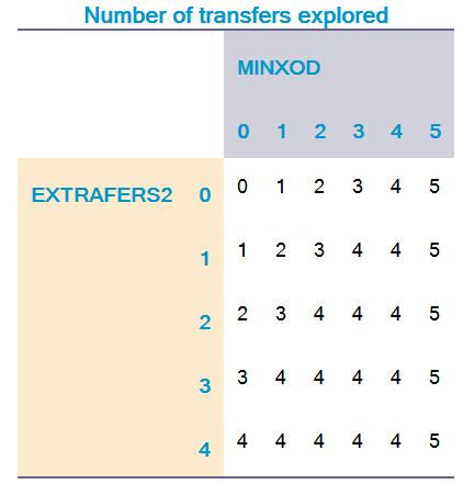
For example, suppose MAXFERS=5, EXTRAXFERS1=4 and EXTRAXFERS2=2. If O-D pairs have minimum-cost routes with 0, 1, or 2 transfers, the program will explore routes with up to 2, 3, or 4 transfers (the MINXOD+**EXTRAXFERS2** constraint applies). If O-D pairs have minimum-cost routes with 3 or 4 transfers, the program explores routes with up to 4 transfers (the EXTRAXFERS1 constraint applies). Finally, for O-D pairs that have minimum-cost routes with 5 transfers, the program explores 5 transfers (the MAXFERS constraint applies).
Thus, the program explores more routes for directly connected zone pairs than for less directly connected zone pairs. This is consistent with observed travel patterns: 70-80% of trips are completed within two transfers or three transit legs. The program expends more effort where travelers make a greater proportion of tips.
Defines fare systems that the program uses to calculate trip fares. Keywords and sub-keywords include:
Use separate FARESYSTEM statements to define multiple fare systems in public transport network.
You input the FARESYSTEM statements to the Public Transport program with the FILEIFAREI file. The program uses fare systems for the evaluation, skimming, loading, and loading-analyses processes. The program does not use fares in enumeration.
The program allocates fare systems to lines, either indirectly through transit modes and operators with FACTORFARESYSTEM, or directly with the LINE control statement.
When modeling fares, you must allocate all lines to fare systems; travelers incur fares when using the lines. You can code a NULL fare system to run lines effectively free.
Fare systems define the cost of:
-
Travel on lines
-
Boarding the first line of a trip
-
Boarding second and subsequent lines
-
Transfers between lines with the same or different fare systems
See Fares for a description of fares modeling.
Example 1: Distance with IBOARDFARE + UNITFARE + SAME=SEPARATE
FARESYSTEM NUMBER=4,
NAME=DISTANCE,
LONGNAME="WITHOUT FAREFROMFS",
STRUCTURE=DISTANCE, SAME=SEPARATE,
IBOARDFARE=1.35,
UNITFARE=0.83
Example 2: Zone based FROMTO fare system with no FAREFROMFS
FARESYSTEM NUMBER=8,
NAME="FAREZONE-FROMTO",
LONGNAME="WITH FROM-TO FARES",
STRUCTURE=FROMTO, SAME=CUMULATIVE,
FAREFROMFS=10*0,
FAREMATRIX=FMI.1.1,
FAREZONES=NI.FAREZONE
FARESYSTEM Keywords
-
FAREFROMFS - |RVn|4 - Optional. Fare incurred when transferring from fare systems defined by other FARESYSTEM control statements to this fare system. You can also provide the cost of transferring between the same fare system, and incentives (that is, negative fares) between select fare systems.
For example, consider:
FARESYSTEM NUMBER=3
FAREFROMFS=45, 70, 30
The costs of transferring from fare systems 1, 2, and 3 to fare system 3 are 45, 70, and 30 monetary units, respectively.
You can include boarding fares applicable at transfers in FAREFROMFS. You must code FAREFROMFS in monetary units; the program converts to generalized cost with VALUEOFTIME.
The default value is 0.
-
FAREMATRIX |S| - Optional. Name of the fare matrix for this fare system. Must be input with FILEIFAREMATI.
FAREMATRIX is required for STRUCTURE=HILOW or STRUCTURE=FROMTO statements, and cannot be used for any other types.
For STRUCTURE=HILOW, the row of the matrix represents the lowest fare zone traversed, and the column the highest fare zone traversed.
For STRUCTURE=FROMTO, the row of the matrix represents the boarding fare zone traversed, and the column the alighting fare zone traversed.
The program converts the fare, derived from FAREMATRIX, into generalized cost with VALUEOFTIME.
Valid strings are standard matrix names of the type: FM.#.# or FMI.#.Name.
-
FARETABLE - |RKV32000| - Optional. List of X- and Y-coordinates that define the table used to compute fares for a trip’s "length" component (rather than boarding or transfer components). Other mechanisms available are UNITFARE and FAREMATRIX. You can use fare tables when STRUCTURE is DISTANCE, COUNT, or ACCUMULATE.
In the coordinates, the X-axis represents trip length and the Y-axis represents the fare, in monetary units. For example, if STRUCTURE is DISTANCE, the X-axis represents distance and the Y-axis represents fare.
Separate each pair of X and Y values with a comma or hyphen. Separate each pair of coordinates with a comma.
For example:
FARESYSTEM NUMBER=11,
NAME="FAREZONE-COUNT", LONGNAME="WITH
FARE ZONES",
STRUCTURE=COUNT, SAME=CUMULATIVE,
FAREZONES=NI.FAREZONE,
FARETABLE=1-1.00, 2-1.75, 3-2.85, 4- 4.10, 5-5.5
or
FARETABLE=1,1.00, 2,1.75, 3,2.85, 4,4.10, 5,5.5,
When STRUCTURE is DISTANCE, the curve runs parallel to the X-axis up to the first coded point and beyond the last. Thus, if the measure of trip length is less than the first coded value of X, the fare is the first coded fare. If the measure of trip length is greater than the last coded value of X, the fare is the last coded fare. The fare, Y, must always be greater than zero, and either stay the same or increase with trip length; the fare can never decrease.
When STRUCTURE is COUNT, X values must range from 1 to the number of fare zones and increase monotonically. The fare, Y, must always be greater than zero and increase with trip length.
When STRUCTURE is ACCUMULATE, X values must range from 1 to the number of fare zones and increase monotonically. The fare for each zone must be greater than zero.
The program converts the fare derived from FARETABLE into generalized cost with VALUEOFTIME.
-
FARETABLE - INTERPOLATE - |?| - Optional. Flag that specifies interpolation between coded points in the fare table. There are two possible values:
For example, consider:
FARESYSTEM NUMBER=2 LONGNAME="ALL"
NAME="ALL"
STRUCTURE="DISTANCE",SAME=SEPARATE,
FARETABLE=2.5,0.50, 4.0,0.60,
10,1.2,15,1.50 INTERPOLATE=T
The fare would be 0.70 for a 5-km trip, 1.10 for a 9-km trip, and 1.32 for a 12-km trip. However, if INTERPOLATE was F, the fare would be 0.60 for both the 5-km trip and the 9-km trip, and 1.20 for the 12-km trip.
INTERPOLATE only applies if STRUCTURE is DISTANCE. If STRUCTURE is COUNT or ACCUMULATE, the program assume the curve is a step function.
Default value is F.
-
-
FAREZONES |S| - Name of node variable in the input network file that contains the node’s fare zone number. Required if STRUCTURE is HILOW, COUNT, FROMTO, or ACCUMULATE.
Fare zones may represent groups of nodes or single nodes. The technique for grouping nodes into fare zones depends on the fare zone system used. If STRUCTURE is HILOW, you must use an annular grouping. If STRUCTURE is COUNT, FROMTO, or ACCUMULATE, you use sequential grouping.
Valid strings are standard names for node variables of the type: NI.Name.
-
IBOARDFARE |R| - Optional. Fare incurred upon boarding the first transit leg of a trip. A transit leg might take a part or the entire length of a line. The program uses the fare system of the line on which the traveler completes the first leg.
You must code IBOARDFARE in monetary units. The program converts the fare into generalized cost with VALUEOFTIME.
The default value is 0.
-
LONGNAME - |S| - Optional. Second unique string identifier for a user- defined fare system.
-
NAME - |S| - Optional. Unique string identifier for a user-defined fare system.
-
NUMBER - |I| - Unique numeric identifier for a user-defined fare system.
Valid values range from 1 to 1999.
-
STRUCTURE - |S| - Measure unit for trip length, used to compute fares.
Possible values include:
-
FLAT — Trip length is not relevant for this fare structure. Calculate fare from IBOARDFARE and FAREFROMFS.
-
DISTANCE — Trip length is in-vehicle distance, measured in user-specified units (such as miles or kilometers).
-
HILOW — Trip length is the difference between the highest and lowest fare zones crossed during the trip (an annular fare zone structure)
-
COUNT — Trip length is a measure of the number of fare zones crossed (a sequential fare zone structure).
-
FROMTO — Trip length is an attribute of the boarding and alighting fare zones.
-
ACCUMULATE — Trip length is the number of fare zones crossed. Each fare zone has an associated fare which is accumulated as the zone is traversed. This differs from COUNT, where the fare is calculated at the end of the leg or trip from the total number of fare zones traversed.
-
FREE — Defines a NULL fare system; lines with such systems give free rides. Use with caution. For this value, do not code any other FARESYSTEM keywords.
Data requirements of fare systems vary with STRUCTURE. See Fares.
-
STRUCTUR - SAME - |S| - Optional. String that indicates how the program calculates the fare for consecutive legs of a trip with the same fare system. Possible values:
-
CUMULATIVE — Treat consecutive legs as one leg when calculating fare
-
SEPARATE — Calculate the fare for each leg separately
The default value is CUMULATIVE.
-
-
UNITFARE - |R| - Optional. Cost per unit of the measure defined in STRUCTURE.
For example, if STRUCTURE is DISTANCE, the trip cost is UNITFARE * trip distance + boarding and transfer fares.
Code in monetary units. The program converts to generalized cost with VALUEOFTIME.
Default value is 0.
-
Footnotes
n - is number of fare systems
Note: Note
See FILEI for general information about FILEI and for important limitations when using Application Editor.
Specifies files that may be input to the Public Transport program. Keywords and sub-keywords include:
All FILEI keywords are "trigger" keywords and need not be preceded by the control statement name.
Note: The Public Transport program allows certain types of files to have multiple files. For example LINEI can have up to 32 files. Due to a restriction on the total number of files, fewer files than permitted for a particular file type may be active in Application Editor.
FILEI Keywords
-
FACTORI - |FKVu|[filei-1] - Optional. Specifies the names of the input factor files. You must code explicitly for each user class, though you can assign the same file to two or more classes.
You may input up to ten input factor files, one per user class. Specify an index, [#], for each, corresponding to the classes defined by PARAMETERSUSERCLASSES statement. If there is no index, the program assumes it to be 1.
FACTORI is required for the route-enumeration, route- evaluation, loading, and loading-analyses processes. However, if you input a Public Transport network with NETI, do not specify FACTORI because the network contains FACTOR data.
Example: FACTORI for USERCLASSES=1,3-4. User class 3 and 4 use the same factors.
FILEI FACTORI[1]= FACTSUC1.FAC,
FACTORI[3]=FACTSUC3.FAC,
FACTORI[4]=FACTSUC3.FAC
See FACTORS for a list of keywords you can use.
-
FACTORI - LIST - |?| - Optional. Flag that indicates whether to list the lines file as input.
Y — List the lines file as input.
N — Do not list the lines file as input Default value is N.
-
FACTORI - MAXERRS - |I| - Optional. Maximum number of errors allowed in the factor file before the program stops processing factors.
Default value is 0.
-
FACTORI - OMITFARES - |?| - Optional. Flag that indicates to validate fare data in the factor file. Possible values:
Y — Omit validation of fare-related data in the factor file. The output network file may not be suitable for use with fares in subsequent runs of the Public Transport program.
N — Validate fare-related data in the factor file.
Default value is N.
-
-
FAREI - FK| - Optional. Name of input file defining the fare systems. The file contains one or more FARESYSTEM control statements.
Required if the program will consider fares during route- evaluation and skimming processes.
See FARESYSTEM for a list of keywords you can use.
-
FAREMATI - |FKV| - Optional. Name of the input file that contains one or more matrices used for computing fares.
You may input up to 99 files. Append an index to each. If you do not specify an index, the program assumes the index is 1.
Input files may contain either standard CUBE Voyager binary matrices or records containing matrix data in the pattern:
M, I, J, f[j],f[j+1]....f[j+n]
where:
-
M - Either a name or number, depending upon how you specify FARESYSTEM FAREMATRIX. If FAREMATRIX=FMI.x.name, then M must match name. If FAREMATRIX=FMI.x.y, then M must be the table number, y (x specifies the FAREMATI index.).
-
I - Row number. There must be a row for each fare zone that will use the matrix.
-
J - Column number for the 1st f[j] that follows.
-
f[j] - Fare for line j, followed by the fare for line j+1 and so on. There may be multiple records for a line.
Delimit files with either commas or white space.
-
-
LINEI - |FKVf|[filei-2] - Optional. Name of input file containing lines. The file can contain lines in CUBE Voyager format (that is, described with the LINE control statement), or in TP+ format. You must convert any lines files in TRIPS format to CUBE Voyager format. To input the lines from a CUBE geodatabase stored in an MDB file, specify the file name followed by a backslash and the name of the geodatabase feature class.
You may input up to 32 lines files. Append an index to each. Without an index, the program assigns an index of 1. Therefore, if inputting only one file, you need not specify an index. Indexes need not be monotonic or sequential.
LINEI is required for the route-enumeration, route- evaluation, loading, and loading-analyses processes. However, if you input Public Transport network with NETI, do not specify LINEI should not be specified because the network contains line data.
See LINE for a list of keywords you can use. Valid index numbers range from 1 to 32.
Note: LINEI can read, at maximum, two decimal places for input values. If more decimal places are specified, CUBE will round the outputs. Please see Considerations on numeric formats.
-
LINEI - LIST - |?| - Optional. Flag that indicates whether to list the lines file as input. Possible values:
Y — List the lines file as input.
N — Do not list the lines file as input
Default value is N.
-
LINEI - MAXERRS - |I| - Optional. Maximum number of errors permitted in lines files. When errors exceed this number, the program stops processing lines.
Default value is 0.
-
LINEI - SKIPBADLINES - |?| - Optional. Flag that indicates whether to treat data errors as warning. Possible values:
Y — Downgrade data errors found when reading lines data to data warnings. The program will be able to read the entire input file without termination due to data errors.
N — Treat data errors as errors.
The default value is the value of PARAMETERS SKIPBADLINES.
-
-
LOOKUPI - |FKV999| - Optional. Name of file containing records for a lookup function implemented with the LOOKUP control statement.
Equivalent to the FILE keyword of the LOOKUP control statement. You must index LOOKUPI.
-
MATI - |FKVf|[filei-2] - Optional. Name of an input matrix file.
You can define up to 10 matrix files to input. If you do not specify an index, the program assumes the index is 1.
The Public Transport program only requires trip matrix files for the loading process. Because the run can compute trips, you need not input trip matrix files. Therefore, you can use the MATI keyword to input any type of matrix data into working matrices, and then manipulate, report, and output the data with MATO.
Index values can range from 1 to 10.
For example:
FILEI MATI[1]= TRIPSUC1.MAT,
MATI[3]=TRIPSUC3.MAT,
MATI[4]=TRIPSUC3.MAT
This statement names the input matrix files; the PARAMETERSTRIPSIJ statement specifies which demand matrix the Public Transport program loads for each user class.
Note: MATI can read, at maximum, two decimal places for input values. If more decimal places are specified, CUBE will round the outputs. Please see Considerations on numeric formats.
-
NETI - |FK| - Name of the input network file.
Files can be produced by the Network program or a previous run of the Public Transport program. Files can be a CUBE binary network file or a CUBE geodatabase network store in an MDB file. If specifying a CUBE geodatabase network, enter the filename followed by a backslash and the name of the CUBE geodatabase network.
Networks produced by the Network program contain just the basic public transport infrastructure, zones, nodes, stops, and links.
Networks produced by the Public Transport program are complete public transport networks. They contain, in addition to the basic infrastructure, all the components that make a public transport network:
-
System data input with SYSTEMI
-
Line data, input with LINEI
-
Factor data, input with FACTORI
-
Nontransit legs, generated with the GENERATE control statement, input with NTLEGI, or both
When produced by a Public Transport run in which trips were loaded, the public transport network may also contain nontransit and transit loads.
Thus, if NETI specifies an input network produced by the Public Transport program, you need not provide SYSTEMI, FACTORI, NTLEGI and LINEI files unless you invoke the Public Transport Network Development function. In this case, the program only takes the basic network infrastructure from the NETI file; you must supply all other components.
Starting with CUBE 6, PT may optionally read station information directly from the network. The station information should be presented by various fields as below:
-
STANUM — Station number, must be unique
-
STAZ — Station zone number
-
MAXD — Maximum distance * 100 for each station
-
SPACE — Number of parking spaces
-
STACOST_AM — Station parking cost (AM)
-
STACOST_MD — Station parking cost (MD)
-
STAW_PNR — Station terminal time (PNR)
-
STAW_KN — Station terminal time (KNR)
-
TSTYPE — Station type
-
STA_NAME — Station name
-
N — Station node number (Same as network node #)
-
-
NTLEGI - |FKVf|[filei-2]Optional. Name of input files containing nontransit legs.
To input the nontransit legs from a CUBE geodatabase stored in an MDB file, specify the file name followed by a backslash and the name of the geodatabase feature class.
You can define up to 32 input files. Append each keyword with an index, such as NTLEGI[5]. The GENERATE READNTLEGI statement defines valid indexes that the program will process. Indexes need not be monotonic or sequential. If you do not specify an index, the program assumes the index is 1.
See NT for a list of keywords you can use.
Index values can range from 1 to 32.
Note: NTLEGI can read, at maximum, two decimal places for input values. If more decimal places are specified, CUBE will round the outputs. Please see Considerations on numeric formats.
ROUTEI - |FKVu|[filei-1] - Optional. Name of the input route files. Explicitly specify a unique file for each user class.
You can define up to 10 route files to input, one per user class. Append each keyword with the index of the user class. The PARAMETERSUSERCLASSES statement defines user classes. If you do not specify an index, the program assumes the index is 1.
When you define an input route file for a user class, the program bypasses the route-enumeration process for that user class. You can define input route files for some user classes and generate them for other user classes.
Index values can range from 1 to 10 (the number of user classes).
For example, consider:
FILEI ROUTEI[1]= ROUTESUC1.RTE,
ROUTEI[3]=ROUTESUC3.RTE,
ROUTEI[4]=ROUTESUC4.RTE
This statement defines input route files for user classes 1, 3, and 4; each user class has its own route file.
Note: ROUTEI can read, at maximum, two decimal places for input values. If more decimal places are specified, CUBE will round the outputs. Please see Considerations on numeric formats.
-
ROUTEI - I - |IV1000| - Optional. List of origin zones for the route-evaluation, skimming, loading, and loading-analyses processes.
Specify origin zones with single numbers or pairs of numbers separated by a dash. Use commas to delimit each number or pair.
Valid values range from 1 to the network’s highest zone number.
-
ROUTEI - J - |IV1000| - Optional. List of destination zones for the route- evaluation, skimming, loading, and loading-analyses processes.
Specify destination zones with single numbers or pairs of numbers separated by a dash. Use commas to delimit each number or pair.
Valid values range from 1 to the network’s highest zone number.
-
ROUTEI - REPORTI - |IV1000| - Optional. List of origin zones for reporting evaluated routes. The program writes the report to file specified with REPORTO.
Specify origin zones with single numbers or pairs of numbers separated by a dash. Use commas to delimit each number or pair.
Valid values range from 1 to the network’s highest zone number. This keyword requires REPORTJ (see usage example below).
-
ROUTEI - REPORTJ - |IV1000| - Optional. List of destination zones for reporting evaluated routes.
Specify destination zones with single numbers or pairs of numbers separated by a dash. Use commas to delimit each number or pair.
Valid values range from 1 to the network’s highest zone number. This keyword requires REPORTI (above). For example:
FILEO ROUTEO[1] =
"{CATALOG_DIR}\EVALROUTES.RTE",
REPORTI=1-2299, REPORTJ=1-2299
See Evaluated routes for an example of the generated report.
-
ROUTEI - SELECTBYMAT - |S| - Optional. Matrix used to produce I and J selections such that the program only performs the evaluation, skimming, loading, and loading-analyses processes for Is and Js that have trips from and to them. Normally, you specify the trip matrix being loaded. For example, MI.x.NAME.
You can use another filter so the program performs the processes only for the I-J pairs that have trips between them:
PROCESS PHASE=SELECTIJ
IF(TRIPSIJ==0)CONTINUE
ENDPROCESS
You can use the I, J, and SELECTBYMAT subkeywords together. The program merges them to produce the final I and J lists.
-
ROUTEI - TRACEI - |IV1000| - Optional. List of origin zones for printing evaluated routes. Routes are reported in the file specified by REPORTO, using the tabular-format route report.
Specify origin zones with single numbers or pairs of numbers separated by a dash. Use commas to delimit each number or pair.
Valid values range from 1 to the network’s highest zone number.
-
ROUTEI - TRACEJ - |IV1000| - Optional. List of destination zones for printing evaluated routes using the tabular-format route report.
Specify destination zones with single numbers or pairs of numbers separated by a dash. Use commas to delimit each number or pair.
Valid values range from 1 to the network’s highest zone number.
- SCREENLINEI - |FK| - Optional. Name of a screenline file that produces intercept data for Public Transport matrix estimation. You can create the file with CUBE or a text-file editor. The file must use the "link-count" format used by CUBE Analyst’s Matrix Estimation program; the turns-count format is not supported. The file contains the definition of the screenlines (in terms of constituent links), along with link count and confidence-interval data.
-
SYSTEMI - |FK| - Name of the input file containing public transport system data.
This file contains data for modes, operators, and wait curves, as described in the MODE, OPERATOR, and WAITCRVDEF control statements.
-
TURNPENI - |FKV2| - Optional. Names of one or two turn-penalty files. Usually written by the Highway program, these files contain records detailing turn penalties or prohibitions.
Turn penalty movement records have the following format:
A B C Set Penalty
where:
-
A is the entry node to the intersection
-
B is the intersection node
-
C is the exit node.
-
Set is a number in the range 1-8; you select which sets the model uses.
-
Penalty is either -1 to indicate a prohibited turn in the Highway model or the value of the junction delay, measured in minutes.
You can enter one set per record. Separate the data fields in a record with white space (either a space or a comma).
Turn penalty movement records cannot contain function specifications.
Most model runs that incorporate junction delays require one turn-penalty input file. However, for forecast years, model runs require two turn-penalty input files, one with base-year delays and one with forecast-year delays. For such runs, you support an incremental approach for forecast years by controlling a line’s travel times with RUNTIME RT or NNTIME.
Note: As transit vehicles follow user-defined routes (which can differ from general traffic), they ignore banned turns and only use the junction delay data.
TURNPENI can read, at maximum, two decimal places for input values. If more decimal places are specified, CUBE will round the outputs. Please see Considerations on numeric formats.
-
-
TURNPENI - BASEDATA - |?| - Optional. Flag indicating whether turn penalty file contains base-year junction delays. Possible values:
-
T — File contains base-year junction delays. The program uses this file to obtain scaling values, which scale transit-line travel times to RUNTIME, RT, and NNTIME values.
-
F — File does not contain base-year junction delays.
Default value is F.
When applying the incremental approach to junction delays, the program reads two turn-penalty files. Set BASEDATA to T for the file containing the base-year junction delays, and to F for the other file, which contains forecast-year turn penalties.
-
-
TURNPENI - LIST - |?| - Optional. Flag indicating whether to generate a report of turn-penalty values. Possible values:
-
T — Program prints a report that lists turn-penalty values used. When the MAXLINKDELAY subkeyword limits values, the report lists the value read from the file and value the model run used.
-
F — Program does not print a report that lists turn- penalty values used.
Default value is F.
-
-
TURNPENI - MAXLINKDELAY - |SVn|[filei-3] - Optional. Name of a link variable that contains the maximum delay values (measured in minutes) permitted on each link in the network.
You can reference the variable as li.VarName orlw.VarName; alternatively you can have the program read the variable from the input network by setting MAXLINKDELAY=MaxDelay.
Use this keyword to limit the junction delay a transit vehicle experiences at a particular turn or junction. The Highway program assumes that all turning vehicles are equally delayed. Therefore, use this keyword when modeling provisions, such as bus-only lanes, that reduce delays to public transit vehicles at turns.
The link variable must specify large values (for example, 999) for links without bus-only lanes or other delay- reduction measures; setting its value to zero would eliminate junction delays for that link.
-
TURNPENI - MISSINGLINK - |I| - Optional. Integer that specifies the error handling when the input network does not contain a link specified in the turn penalty file. Possible values:
-
0 — Program ignores such errors.
-
1 — Program prints a warning message.
-
2 — Program generates a fatal error message.
Default value is 0.
-
-
TURNPENI - NOTMODES - |I| - Optional. List of transit modes that do not have turning penalties. By default, input turn-penalty values apply to all transit modes.
Valid values range from 0 to 999. Default value is 0.
-
TURNPENI - SETS - |I| - Optional. Set numbers from the turn-penalty file that the program includes in the run; the program discards any non-matching set numbers.
If a turn has several records, the program selects those matching the SETS list. The program uses the record with the highest set number among those selected.
When you specify the default value, the program selects movements from all sets. When a movement has multiple records, the program uses the record with the highest set number.
Valid values range from 0 to 8. The default value is 0.
Footnotes
FILEI u represents user class
f represents file number
n represents name of link variable
Example
//Some files that may be input to PT
FILEI FACTORI = factor.fac, list=t
LINEI[1] = lines.lin, list=t
NETI = inetwork.net
NTLEGI = geno.ntl
Specifies files that the Public Transport program outputs.
All FILEO keywords are "trigger" keywords and need not be preceded by the control statement name. Keywords and sub- keywords include:
Note: The Public Transport program allows certain types of files to have multiple files. For example PRINTO can have up to 99 files.
However, Application Editor restricts the total number of files. Therefore, fewer files than permitted for a particular file type may be active in Application Editor at any point.
FILEO Keywords
-
INTERCEPTO - |FKV10| - Optional. Name of an output intercept file. This file details which origin-destination pairs have routes that cross the screenlines. CUBE Analyst uses this file along with its associated screenline file when estimating matrices.
You can define up to 10 intercept files to output, one per user class. Append each keyword with the index of the user class. The PARAMETERS USERCLASSES statement defines user classes. If you do not specify an index, the program assumes the index is 1.
Runs that create matrix estimation intercept data should either read a single screenline file, which provides link and count information for the screenline, or write one or more screenline files (one for each user class), which contain link and count information obtained from the input network.
-
LINEO - |FK| - Optional. Name of the output lines file. This file lists all the lines in the public transport system, in the LINE control statement format.
To output the lines to a CUBE geodatabase stored in an MDB file, specify the file name followed by a backslash and the name of the geodatabase feature class. Must be the same geodatabase specified in NETI or BASEGDBNETWORK.
Note: LINEO can save at maximum two decimals for travel time values. Considerations on numeric formats.
-
LINEO - BASEGDBNETWORK - |S| - Optional. Name of the geodatabase base-highway network associated with the output lines file. This network must be consistent with the lines data. Typically, you reference the network used as input in the step that produced the lines.
If NETI specifies a geodatabase network, you need not specify a value; CUBE Voyager uses that network as the base-highway network. The value for this keyword can be a full path to the location of the highway network or, just the name of the network, if the network is located in the same geo- database as the FILEO location.
-
LINEO - NET - |S| - Optional. Specifies whether the output lines file contains lines from the output network or the input network. Possible values:
I — Program lists lines in the input network.
O — Program lists lines from the output network.
Input and output networks have identical line attributes and node lists, but the loads can vary depending upon the options selected.
The default value is O.
-
LINEO - VOL - |?| - Optional. Flag that indicates whether to include loading results (that is, boardings, alightings, and line and link loads). Possible values:
Y — Include loading results with lines data.
N — Do not include loading results with lines data.
Default value is Y.
-
-
LINKO - |FKV4| - Optional. Name of output links file. This file contains all nontransit legs and transit links. You can specify a DBF file or an MDB file.
To output the links to a CUBE geodatabase stored in an MDB file, specify the file name followed by a backslash and the name of the geodatabase feature class.
You can specify up to four files. Each file might contain different outputs from a single run of the program.
The standard output contains data on the following link attributes:
-
A-node
-
B-node
-
Mode number
-
Name of line traversing link (for nontransit legs, this is the mode name)
-
Distance
-
Time
-
SEQ —Sequence number of this line among the lines that traverse the link; ranges from 1 to CNT)
-
CNT — Number of lines that traverse this link
-
HEADWAY — Headway of the line in the specified HDWAYPERIOD
-
Load (if the public transport network contains loads)
When multiple lines traverse a link, the output contains one record for each line.
Note: LINKO can save at maximum two decimals for travel time values. Considerations on numeric formats.
-
LINKO - BYCLASS - |?| - Optional. Flag indicating whether outputs are summed by user class in the links file. Possible values:
Y — Program writes the run totals, summed by user class, and the attributes used in the run for each user class. User class–specific fields have names with suffixes, like _1 and _2.
N — Program writes data not separated by user class
Default value is N.
-
LINKO - DISTDEC - |I| - Optional. Specifies the number of decimal places to use for the network link distance in the output file. This setting does not apply to non-transit links. Non-transit links are always rounded to 2 decimal places.
Values in the range 0-2 are valid.
Default value is 2.
-
LINKO - FMVOLS - |?| - Optional. Flag indicating whether outputs from a crowding run contain demand volumes or flow- metered volumes. Possible values:
Y — Program writes the flow-metered volumes from the crowding run.
N — Program writes the loaded volumes (represents the demand volumes for crowding runs).
Default value is N.
-
LINKO - FORMAT - |S| - Sets the file format of LINKO file. Possible vaules are:
TXT — Fixed format text file
DBF — PIndustry-standard database file
CSV — Comma separated values in plain-text form
Note
If the output is in GIS database (.mdb), the FORMAT value is ignored. If FORMAT is not specified, the default format will be DBF.
-
LINKO - LINES - |?| - Optional. Flag indicating whether lines data is included in the output links file. Possible choices:
Y — Include line per link data.
N — Do not include line data.
Default value is Y.
-
LINKO - NTBYLINK - |?| - Optional. Flag indicating treatment of nontransit legs in output file. Possible values:
Y — Converts records of nontransit legs to the corresponding sequence of underlying links in the network (as defined by the XN keyword in the NTLEG control statement). From the output, you can obtain true nontransit loads for walk links, and so forth.
N — Does not convert records of nontransit legs.
Default value is N.
-
LINKO - NTLEGS - |?| - Optional. Flag indicating whether to include nontransit legs in output file. Possible values:
Y — Include nontransit legs in output file
N — Do not include nontransit legs in output file
Default value is Y.
-
LINKO - ONELINKREC - |?| - Optional. Flag that indicates whether the program combines transit data per highway link. Possible choices:
Y — Output file contains one record for each highway link. When multiple transit lines traverse a single link, the file summarizes the data, combining headways and summing volumes. The output contains the following fields:
-
DIST — Link length
-
LINECNT — Count of lines traversing the link
-
PERHOUR — Total services traversing the link per hour in the specified HDWAYPERIOD
-
TVOL — Transit loading for the link
-
NTVOL — Nontransit load on the link
With one record for each highway link, you can easily merge data into the highway network for graphic displays.
N — Output file contains one record for each transit line traversing a highway link. Multiple transit lines traversing the same highway link result in multiple records for a highway link.
Typically, you use this keyword when NTBYLINK is set to Y. Do not use ONELINKREC when ONOFFS is set to Y.
Default value is N.
-
-
LINKO - ONOFFS - |?| - Optional. Flag indicating whether to include boardings and alightings. Default value is N.
When set to Y, program includes boardings and alightings at each stop in output file. The file format differs from the standard output, and instead contains the following attributes:
-
MODE
-
OPERATOR
-
NAME — Line name
-
LONGNAME
-
DIST — Link length
-
TIME — Time needed to traverse the link
-
LINKSEQ — Sequence number of this link within the route taken by the line
-
HEADWAY — Headway of the line in the specified HDWAYPERIOD
-
STOPA — 1 if the line stops at the A-node; 0 otherwise.
-
STOPB — 1 if the line stops at the B-node; 0 otherwise
-
VOL* — Transit load using this line on this link.
-
ONA* — Boardings at the A-node
-
OFFA* — Alightings at the A-node
-
ONB* — Boardings at the B-node
-
OFFB* — Alightings at the B-node
-
REV_xx* — Link values for volume, ons, and offs in the reverse direction of travel. These are only nonzero values for lines that have ONEWAY set to F. In the reverse direction of travel, travelers reach the B-node before the A- node.
The data records are in line-order (and stop-order within line). Output may be produced for run totals and individual user classes in a run (see BYCLASS).
Do not use ONOFFS when ONELINKREC is set to Y.
-
-
LINKO - SKIP0 - || - Optional. Flag indicating whether to omit links with zero loads from output file. Possible values:
Y — Omit nontransit legs and lines and links with zero loads from output file
N — Include nontransit legs and lines and links with zero loads in output file
Default value is N.
-
LINKO - TIMEDEC - || - Optional. Specifies the number of decimal places to use for the network link travel time in the output file. This setting does not apply to non-transit links. Non-transit links are always rounded to 2 decimal places.
Values in the range 0-5 are valid.
Default value is 2
-
LINKO - VOLFIELDS - || - Optional. Flag indicating whether to include volume fields in output file. Possible values:
Y — Include volume fields associated with total loadings. If there are no loadings, then fields contain zero values.
N — Omit volume fields from output files.
Default value is Y.
-
-
MATO - |FKV10| - Optional. Name of an output matrix file. Explicitly specify a unique file for each user class.
You can define up to 10 matrix files to output, one per user class. Append each keyword with the index of the user class. The PARAMETERSUSERCLASSES statement defines user classes. If you do not specify an index, the program assumes the index is 1.
The Public Transport program produces skim and select link-analysis matrices, but other types of matrices, either generated or input with MATI, may be manipulated and output with MATO.
For example, consider:
FILEO MATO[1]= SKIMUC1.MAT,
MATI[3]=SKIMUC3.MAT,
MATI[4]=SKIMUC4.MAT
This statement generates output matrix files for user classes 1, 3, and 4.
-
MATO - DEC - |SV*255| - Optional. String that specifies the numeric format of the working matrices written to the output matrix file. Specify a separate DEC for each MO. Valid values:
-
0-9 — Convert output matrix cells to integers, preserving indicated number of decimal places.
-
S — Store cells in single-precision floating- point format.
-
D — Store cells in double-precision floating- point format.
Default value is 2.
Please see Considerations on numeric formats.
-
-
MATO - MO - |IVP255| - Lists the working matrices (MWs) included in the output matrix file.
You may index MO. The highest implicit or explicit index determines the number of matrices included in the file. If you do not define a value for an index, the program outputs a dummy matrix. You may specify the same working matrix for more than one index.
The program numbers output matrices sequentially beginning with 1.
For example, consider:
MO=1-5,11-15, MO[20]=1, MO[19]=31
Given this statement, the program writes 20 matrices. Matrices 11 through 18 will be dummy matrices, because the statement defines no working matrix for these index values.
-
MATO - NAME - |SV255| - Optional. Name of matrix (for TP+ and CUBE Voyager matrices).
Output matrices do not require names, but including names helps document the file. Valid matrix names contain only alphanumeric characters, spaces, and underscores (_). CUBE Voyager programs reading the file can reference the matrices by name and/or number.
-
MATO - TYPE - |S| - Optional. String specifying the format of the output matrix file. Possible values:
-
TPP — Standard TP+/CUBE Voyager matrices
-
MINUTP — Standard MINUTP matrices
-
TRANPLAN — Standard Tranplan matrices
-
TXT — ASCII records of matrix values
Default value is TPP.
-
-
MATO - FORMAT - |S| - Optional. String specifying the format of the output matrix file. Possible values:
-
TPP — Standard TP+/CUBE Voyager matrices
-
MINUTP — Standard MINUTP matrices
-
TRANPLAN — Standard Tranplan matrices
-
TXT — ASCII records of matrix values
Default value is TPP.
-
-
-
NETO - |FK| - Name of the output network file, in the format of CUBE binary network (*.NET).
The Public Transport program outputs a complete public transport network containing the following components:
-
Basic network infrastructure of zones, nodes, and links, produced by the Network program
-
System data, input with SYSTEMI
-
Line data, input with LINEI
-
Factor data, input with FACTORI
-
Nontransit legs, generated with the GENERATE control statement, input with NTLEGI, or both
If produced by a run of the Public Transport program in which trips were loaded, the public transport network may also contain nontransit and transit loads.
You can input this network to the Public Transport program with NETI, in which case the file does not require SYSTEMI, FACTORI, NTLEGI and LINEI files, unless you invoke the Public Transport network- development process.
-
NETO - DEC - |S| - Optional. String that specifies precision for storing transit and nontransit loads in the network. Possible values:
0-9 — Convert loads to integers, preserving at least the given number of decimal places
S — Store cells in single-precision floating- point format
D — Store cells in double-precision floating- point format
The value of impacts the space required to store the output network. Integer values require the least space and preserve precision to the number of decimal places specified by DEC. Single-precision values take up four bytes and retain precision up to 6 or 7 decimal places. Double-precision values require eight bytes and preserve full precision. Default value is 2.
Please see Considerations on numeric formats.
-
-
NTLEGO - |FK| - Optional. Name of output nontransit legs file.
To output the nontransit legs to a CUBE geodatabase stored in an MDB file, specify the file name followed by a backslash and the name of the geodatabase feature class. Must be the same geodatabase specified in ref:NETI <ptp-cs-filei-neti> or BASEGDBNETWORK.
This file contains all the nontransit legs in the public transport system, in the nontransit control- statement format.
-
NTLEGO - BASEGDBNETWORK - || - Optional. Name of the geodatabase base-highway network associated with the nontransit legs file. This network must be consistent with the nontransit legs data. Typically, you reference the network used as input in the step that produced the legs.
If ref:NETI <ptp-cs-filei-neti> specifies a geodatabase network, you need not specify a value; CUBE Voyager uses that network as the base-highway network. The value for this keyword can be a full path to the location of the highway network or just the name of the network, if the network is located in the same geo- database as the FILEO location.
-
NTLEGO - NET - |S| - Optional. String indicating whether to include nontransit legs from the output network or input network. Possible values:
O — Include nontransit legs from the output network in the nontransit legs output file.
I — Include nontransit legs from the input network in the nontransit legs output file.
Both files contain identical attributes for nontransit legs, but the loads might vary, depending on the options selected.
Default value is O.
-
NTLEGO - VOL - |?| - Optional. Flag indicating whether to include loads with nontransit legs. Possible values:
Y — Write loads with nontransit legs.
N — Do not write loads with nontransit legs.
Default value is Y.
-
NTLEGO - XN - |?| - Optional. Flag indicating whether to output nodes. Possible values:
Y — Output any nodes between the start and end nodes of nontransit legs. See XN under NT.
N — Do not output nodes between the start and end nodes of nontransit legs.
Default value is Y.
-
-
PRINTO - |FK| - Optional. Name of an output file, which you have defined in a PRINT FILE control statement.
Use the PRINT control statement to format data items and write them as a single line to the standard printed output, to a file, or to both the standard output and a file.
-
REPORTO - |FK| - Name of the file to which the program writes reports from the route-enumeration and route- evaluation processes.
All diagnostics from these processes are output to the standard Public Transport–program print file.
-
ROUTEO - |FKVu|[fileo-1] - Optional. Name of output file containing enumerated routes. Explicitly specify a unique file for each user class.
You can define up to 10 output files, one per user class. Append each keyword with the index of the user class. The PARAMETERS USERCLASSES statement defines user classes. If you do not specify an index, the program assumes the index is 1.
The statement ROUTEO[x] invokes the route- enumeration process for user class x. You can input previously created enumerated-route files for some user classes and build files for other user classes in the same run.
-
ROUTEO - I - |IV1000| - Optional. List of origin zones for which the program enumerates routes and saves.
Specify the list as a set of single numbers or dash- separated pairs of numbers that give a range. Delimit each number or pair with a comma.
Valid values range from 1 to the network’s highest zone number. By default, the program enumerates and saves routes originating from all zones.
-
ROUTEO - J - |IV1000| - Optional. List of destination zones for which the program enumerates routes and saves.
Specify the list as a set of single numbers or dash- separated pairs of numbers that give a range. Delimit each number or pair with a comma.
Valid values range from 1 to the network’s highest zone number. By default, the program enumerates and saves routes bound for all zones.
-
ROUTEO - REPORTI - |IV1000| - Optional. List of origin zones for which the program reports enumerated and evaluated routes.
Specify the list as a set of single numbers or dash- separated pairs of numbers that give a range. Delimit each number or pair with a comma.
The program only includes route evaluations completed by the skimming, loading, or loading- analyses processes. The program reports routes in the file specified in REPORTO.
Valid values range from 1 to the network’s highest zone number.
-
ROUTEO - REPORTJ - |IV1000| - Optional. List of destination zones for which the program reports enumerated and evaluated routes.
Specify the list as a set of single numbers or dash- separated pairs of numbers that specify a range. Delimit each number or pair with a comma.
See Enumerated routes and Evaluated routes for examples of these reports.
Valid values range from 1 to the network’s highest zone number.
-
ROUTEO - SELECTBYMAT - |S| - Optional. Matrix used to produce I and J selections such that the program enumerates and saves routes only for the Is that have originating trips and the Js that have terminating trips. Normally, specify the trip matrix being loaded. For example, MI.x.NAME.
For the evaluation, skimming, loading, and loading- analyses processes, you can filter to select only those I-J pairs that have trips between them:
PROCESS PHASE=SELECTIJ
  IF(TRIPSIJ==0)CONTINUE
ENDPROCESS
Together, all three subkeywords are merged to produce the final I and J lists.
-
ROUTEO - TRACEI - |IV1000| - Optional. List of origin zones for which the program prints evaluated routes using the tabular-format route report.
Specify the list as a set of single numbers or dash- separated pairs of numbers that give a range. Delimit each number or pair with a comma.
The program reports routes in the file specified in REPORTO.
Valid values range from 1 to the network’s highest zone number.
-
ROUTEO - TRACEJ - |IV1000| - Optional. List of destination zones for which the program prints evaluated routes using the tabular-format route report.
Specify the list as a set of single numbers or dash- separated pairs of numbers that give a range. Delimit each number or pair with a comma.
See Evaluated routes for examples of these reports.
Valid values range from 1 to the network’s highest zone number.
-
-
SCREENLINEO - |FK10| - Optional. Name of the screenline file the program writes from the network data. Explicitly specify a unique file for each user class.
The file contains screenline definitions and count and confidence-level data. You pass this file with an associated intercept file to a CUBE Analyst run to perform matrix estimation tasks.
You can define up to 10 output files, one per user class. Append each keyword with the index of the user class. The PARAMETERS USERCLASSES statement defines user classes. If you do not specify an index, the program assumes the index is 1.
The program ignores this keyword if you specify the SCREENLINEI keyword. CUBE Analyst will read that file instead.
Use subkeywords to specify the source or value of the data fields that the program writes to the file. You can reference variables, such as li.varname or lw.varname. Alternative, you can use a subkeyword to read a variable from the input network, such as CONFAR=varname.
-
SCREENLINEO - CONFVAR - |S| - Optional. Name of the input network’s link variable that contains confidence-level data.
The confidence level is expressed as an integer value, ranging from 1 to 10000.
You must define either CONFVAR or DEFCONF. Use the DEFCONF keyword when a single confidence-level value applies to all links.
-
SCREENLINEO - COUNTVAR - |S| - Name of the input network’s link variable that contains the link-count data.
-
SCREENLINEO - DEFCONF - |I| - Optional. Confidence level that applies to all output links.
If confidence levels vary from link to link (or screenline to screenline), use the CONFVAR subkeyword.
Valid values range from 1 to 10,000.
-
SCREENLINEO - MEUSESNT - |?| - Optional. Flag indicating whether link use is restricted to transit modes. Possible values:
Y — Program creates intercept data, considering link use of all modes (that is, transit and nontransit)
N — Program restricts link use to only transit modes.
Default value is taken from PARAMETERSMEUSESNT, if specified; otherwise Y.
-
SCREENLINEO - SCREENVAR - |S| - Name of the input network’s link variable that contains the screenline number.
This variable has a value ranging from 1 to 9999 when a link forms part of a screenline, and a zero value for all other links.
-
-
STOP2STOPO - |FKV4| - Optional. Name of file where the program saves the results of the stop-to-stop analyses. File is either DBF format or MDB format.
To save results in the CUBE geodatabase (in MDB format), specify the file name followed by a backslash and the name of the geodatabase feature class.
You can specify up to four output files. Therefore, you can output a number of different analyses from a single run of the program. Use subkeywords to select the types of stop-to-stop movements captured. The data saved to the file can relate to a selection of stop-nodes or groups of stop-nodes.
Note: Bentley recommends producing files no larger than 2 GB, the largest size that CUBE Voyager and CUBE Base can properly process.
The saved file contains the following data fields:
-
Origin zone (I)
-
Destination zone (J)
-
From stop group (FROMGROUP)
-
To stop group (TOGROUP)
-
From stop node (FROMNODE)
-
To stop node (TONODE)
-
Mode (MODE)
-
Movement type (ACCUM)
1=FIRSTLAST
2=ADJACENT
3=ALLONOFFS
4=FIRSLASTBYMODE
5=ADJACENTBYMODE
-
Number of passengers ( VOL)
Note: The file contains either FROMGROUP and TOGROUP or FROMNODE and TONODE, but not both. The two sets of data fields are mutually exclusive.
See More on stop-to-stop analysis.
-
STOP2STOPO - ACCUMULATE - |S| - Optional. Specifies types of transit movements included in the stop-to-stop analysis. Possible types include:
-
FIRSTLAST — Movements from a trip’s first node to last node.
-
ADJACENT — Movements and corresponding mode for each leg of a trip.
-
ALLONOFFS — Movements for all on-off combinations.
-
FIRSTLASTBYMODE — Movements from first node to last node on a particular mode, regardless of intervening modes. Must specify MODES subkeyword.
-
ADJACENTBYMODE — Through movements from first node to last node on a particular mode. Must specify MODES subkeyword.
All movement types other than ADJACENT can contain one or more transit legs.
See More on stop-to-stop analysis.
Default value is FIRSTLAST.
-
-
STOP2STOPO - DEC - |I| - Specifies the number of decimal places to use for the passenger volume values in the output file. Values in the range 1-5 are valid. Default value is 2.
-
STOP2STOPO - GROUPEDMODES - |IV999| - Optional. List of numbers the program uses to recode the modes on transit legs before completing stop-to-stop analysis on a route. (Relevant when transit movement type is ADJACENTBYMODE or FIRSTLASTBYMODE).
First number is the mode number assigned during recoding; subsequent numbers are the modes recoded. Thus, any transit legs with modes listed in the second are subsequent positions are assigned to the mode listed first.
For example, consider:
GROUPEDMODES = 3,6,7,8
The program recodes any transit legs using modes 6, 7, or 8 to mode 3.
Valid values range from 1 to the network’s highest mode number.
-
STOP2STOPO - GROUPS - |IV9999| - List of stop-groups for which the program extracts stop-to-stop movements for the ACCUMULATE subkeyword. Identify stop-groups by number.
Stop-groups are either single stop-nodes or a collection of stop-nodes, such as platforms within a station or clusters of bus stops on either side of a road. You define a node’s stop-group number on the input network’s node record in the variable specified in STOPGROUP.
Specify the list as a set of single numbers or dash- separated pairs of numbers that give a range. Delimit each number or pair with a comma.
If you code both GROUPS and NODES, the program outputs stop-to-stop movements for the specified groups that will include only the specified nodes. Thus, you can exclude nodes from their groups. If you do not code NODES, the program includes all nodes belonging to the specified groups in the analysis. Note that the program does not explicitly report nodes in the output file.
Valid values range from 1 to the network’s highest stop-group.
-
STOP2STOPO - LIST - |?| - Optional. Flag indicating whether to list the contents of the DBF file to the printer file. Possible values:
Y — List contents of the DBF file to the printer file
N — Do not list of contents of the DBF file to the printer file
Default value is N.
-
STOP2STOPO - MODES - |IV999| - Optional. List of modes for which the program accumulates stop-to-stop movements when ACCUMULATE is FIRSTLASTBYMODE or ADJACENTBYMODE.
Specify the list as a set of single numbers or dash- separated pairs of numbers that give a range. Delimit each number or pair with a comma.
Valid values range from 1 to the network’s highest mode. Default value is all modes.
-
STOP2STOPO - NODES - |IV9999| - List of stop nodes for which the program extracts stop-to-stop movements for the ACCUMULATE subkeyword.
Specify the list as a set of single numbers or dash- separated pairs of numbers that give a range. Delimit each number or pair with a comma.
This subkeyword is required if GROUPS is not coded.
Valid values range from 1 to the network’s highest node.
-
STOP2STOPO - STOPGROUP - |S| - Optional. Name of the node variable that contains the stop-group number.
If you code GROUPS, you must code STOPGROUP.
For example, with STOPGROUP=SGNAME, then the node variable NI.SGNAME stores the stop-group numbers, used in GROUPS.
When using stop groups, the program reports on intragroup movements, but cannot disaggregate those movements to the nodes in the group.
-
Footnotes
u represents user class
Example
Some files that may be output by the Public Transport program.
FILEO NETO = onetwork.net
REPORTO = reports.prn
ROUTEO = enumroute.rte, I=1,15,24, J=1,24,
REPORTI=1,15,24 REPORTJ=1,9, 15,24
Example of SCREENLINEO & INTERCEPTO
RUN PGM=PUBLIC TRANSPORT

FILEO REPORTO = "PAPTR00B.PRN"
FILEO ROUTEO[1] = "PAPTR00B.RTE"
FILEO SCREENLINEO = "PT ANALYST EXAMPLE\PAPTR00B.DAT",
  SCREENVAR=SCRLNO COUNTVAR=PTCOUNT CONFVAR=PTCONF
FILEO INTERCEPTO = "PAPTR00B.ICP"
FILEI NETI = "PAPTR00D.NET" ; PT network output from PT program

ENDRUN
Considerations on numeric formats
Traditionally planners have maintained most transportation planning matrices in integer format. Advantages included:
-
Integer values take less space than floating point values
-
Matrix values usually can be represented with numbers where a fixed decimal place can be assumed.
In the past, computers could process integers much faster than floating point numbers. However, this is not necessarily true with newer computers.
Single-precision floating point provides only six to seven digits of precision, and cannot always maintain the precision required for certain types of matrices. CUBE Voyager processes all matrices in double-precision (16 digits) format to accommodate a wider range of values, and to not lose precision or accuracy when computing. However, writing double-precision numbers to the matrix files would generate very large files, and in most cases, only a few decimal places are required for each cell value. Therefore, the Public Transport program stores matrix values with a special packing routine that tries to minimize the file’s space requirements.
The Public Transport program tries to convert each number to an integer starting with 0 decimal places and continues with the next power of 10 until it reaches the maximum level specified. The program uses the lowest level that converts to an integer with no loss of precision. If a scaled cell value is too large to fit within a 32- bit integer, the program stores the cell as a double-precision value. If is D or S, the program skips the integer conversion attempt and stores all cells as either 8-byte double values or 4-byte single values. If not specified, defaults to 2.
For example, consider a cell computed as 10/3. The result is 3.33333333…. to sixteen digits. When changed to single precision, the result is accurate to about seven digits, requiring four bytes to store. If converted to an integer while is 0, the result is 3, and the cell would require only one byte to store—a significant reduction. However, that might not be precise enough for the programs that read it. If is 2 for that number, the resulting integer is 333, requiring two bytes to store. Upon reading, another application will automatically restore the number to 3.33. If were S, the value would be stored as a 4-byte single-precision, and if were D, it would be stored as an 8-byte double-precision. The S and D formats require more storage space.
For stop-to-stop analysis, the movement type affects the output records. When the movement type is 4 or 5 (ACCUMULATE is FIRSTLASTBYMODE or ADJACENTBYMODE), the program writes output records that reflect the modes used in the route’s transit legs. The program analyzes a transit route based on the values of other STOP2STOPO subkeywords, and saves the appropriate records.
Use the GROUPEDMODES subkeyword to recode modes prior to transit-route analysis. With this keyword, you can group distinct modes of the route together, allowing them to appear as one mode for analysis and in subsequent data output.
For example, a model might use two or more mode numbers for different types of rail travel. You might be more interested in transfer to or from rail than in changes between the different rail modes. By grouping the discrete rail modes together, you eliminate this detail from the analysis.
Example of ACCUMULATE subkeyword
Suppose you have a five-leg, two-mode trip:
Generates nontransit legs in the public transport network. Keywords include:
You can generate, input, or generate and input nontransit legs.
You can use one or more GENERATE control statements to generate nontransit legs, each with different criteria. Use the READNTLETI keyword to input previously generated and validated nontransit legs or externally generated ones.
The Public Transport program maintains one table of nontransit legs. The program dynamically updates the table while processing GENERATE statements. The program keeps one leg for each A-node–B-node combination in the table—the leg with the lowest EXTRACTCOST, followed by the leg with the lowest distance (DIST), and then the leg with the lowest NTLEGMODE. After processing all GENERATE statements, the program saves the legs in the table to the Public Transport network file specified by NETO and/or the file specified by NTLEGO. If you specify neither file, the program discards the legs at the end of the run.
Use the necessary keywords to control the nontransit link- generating process produced by the GENERATE statement. With this statement, the program:
-
Builds minimum-cost routes between each node specified with FROMNODE to each node specified with TONODE that is a transit stop. The program ignores nodes specified in TONODE that are not stop nodes.
-
Finds transit modes at each node specified in TONODE, computes the cost to the node, and compares the cost to the mode’s MAXCOST. If the cost for at least one of the modes is less than the mode’s MAXCOST and if the specification in DIRECTLINK is satisfied, the program saves the leg.
-
Examines each saved leg, adding acceptable legs to the legs table. The program adds the best leg for a mode, and legs that service that same mode and whose cost does not exceed the cost of the best leg for that mode plus the SLACK for that mode. If SLACK is not specified, the slack for a mode effectively becomes the difference between the best cost and the MAXCOST for the mode. MAXNTLEGS specifies the maximum number of legs the program will generate for a mode from a FROMNODE.
-
Merges legs using any special transaction codes. For example, you might specify that the program replace a generated leg with a longer leg. See NTLEGI under FILEI.
None of the GENERATE keywords are "trigger" keys; you must code all keywords on a GENERATE control statement.
GENERATE statements must be in the DATAPREP phase.
GENERATE Keywords
-
ACCESSLINK - |R| - Optional. One or more access links from park-and-ride facilities to stop nodes.
Specify an access link as:
A-S,cost,distance
where
-
A — Surrogate access point (integer)
-
S — Stop node (integer)
-
cost — Optional. Cost of using this access link (real).
-
distance — Optional. Distance traveled on this access link (real).
Separate each access link with a comma.
If the link does not exist in the network, the program generates the link.
You specify pairs of numbered sets. Paired values indicate the start of new access links. Enter paired values in the correct order to avoid generating an error.
If you specify ACCESSLINK, the program ignores any TONODE keywords. The program obtains the cost from the route to the A-node. If ACCESSLINK provides numeric values for cost and distance, the program adds them to the link’s cost and distance. If ACCESSLINK only contains one value, the program adds that value to the link’s cost.
Valid values for A and S are 1 to the network’s highest node number.
-
-
COST - |N| - Expression for computing network link costs. Used to determine the minimum-cost nontransit legs between the nodes specified in FROMNODE and TONODE (or ACCESSLINK). Enclose expressions in parentheses.
The expression can contain network data items, such as link distance, time, and speed.
The cost of nontransit legs may be the cost on the basis of which they are built or, you can skim the cost specified by EXTRACTCOST from the network links underlying the nontransit legs.
For example, consider:
GENERATE,
COST=li.Distance,
EXTRACTCOST=li.Time,
NTLEGMODE=32
This script fragment generates nontransit legs on the basis of minimum distance, but skims time along the minimum-distance legs and saves as the cost.
To obtain the perceived nontransit cost, you can factor the nontransit leg cost, derived from COST or EXTRACTCOST, with the FACTORSRUNFACTOR control statement, which is specified by mode. The sample script fragment produces nontransit legs with a mode of 32. You can factor with RUNFACTOR[32]=x.x.
The route-enumeration and evaluation processes use perceived (or factored) costs; both actual and perceived costs may be skimmed.
-
DEFDRIVETIME - |R| - To specify default drive-access time used if time from matrix is zero (DEF).
-
DIRECTION - |I| - Optional. Integer indicating direction of the generated nontransit legs. Possible values:
-
2 — Reverse direction, TONODE to FROMNODE
-
3 — Both directions, FROMNODE to and from TONODE Default value is 3.
NoteNote: Forward direction NTlegs are always generated starting at the FROMNODE(s). The reverse direction NTlegs from the same FROMNODE(s) will follow the same links in opposite order. Be aware that PT will add new reverse-direction links to the output links (LINKO) as neccesary to accommodate the NTlegs.
-
DIRECTLINK - |I| - Optional. Maximum number of network links a nontransit leg can traverse.
By default, the program applies no limit to number of links.
-
EXCLUDELINK - |N| - Optional. Expression that computes the network links to exclude from the generation of nontransit legs. Enclose expressions in parentheses.
You may exclude links from the GENERATE process with network data items, such as link distance, cost, and classifiers.
-
EXTRACTCOST - |N| - Optional. Expression that computes the network link costs skimmed from nontransit legs built on the basis of COST. The skimmed costs become the costs of the nontransit legs. Enclose expressions in parentheses.
The expression can use network data items, such as link distance, time, and speed, to compute the cost.
If you do not specify this keyword, the program derives the cost of nontransit legs from the COST keyword.
To compute perceived nontransit costs for use in the enumeration and evaluation processes, you can factor the nontransit leg-cost derived from COST or EXTRACTCOST with the FACTORSRUNFACTOR control statement.
-
FROMNODE - |S| - Optional. Node or list of nodes that program generates nontransit legs from.
You may specify nodes as numeric values or names of variables that store valid numeric values. For example, you might specify:
FROMNODE=1-NUMZONES
Valid values range from 1 to the network’s highest node number.
-
INCLUDELINK - |N| - Optional. Logical expression (following syntax of Control fields) that computes network links included in the generation of nontransit legs. Enclose expressions in parentheses.
The expression can only use numeric network data fields, such as link distance, cost, and classifiers, to determine included links.
For example:
INCLUDELINK = (LI.LINKTYPE=1-32)
INCLUDELINK = (LW.LTYPE=14,20,23,27,28)
INCLUDELINK = (LI.WALKTIME>0)
-
LIST - |?| - Optional. Flag indicating whether to list nontransit legs. Possible values:
Default value is F.
-
MAXCOST - |RVt*|[gen-1] - Maximum cost allowed for a particular transit mode to enable generation of nontransit legs. Specify cost per mode.
The program generates a leg to a TONODE serviced by a transit mode only when the cost to that node is less than the MAXCOST for that transit mode.
You must specify MAXCOST for at least one mode. The default value is 0. Therefore, the program generates no trips to nodes serviced by modes without a MAXCOST specified, unless other non-zero modes service the node.
When determining the maximum cost for a leg, the program uses the mode of the TONODE. However, if the TONODE specifies a zone, the program uses the mode of the FROMNODE.
The value of SLACK affects the value of MAXCOST.
Valid values are 0 to 500 (in the same units specified in COST).
-
MAXNTLEGS - |IVt|[gen-1] - Optional. Maximum number of nontransit legs to generate for a particular transit mode from a FROMNODE to a TONODE serviced by that mode.
Valid values range from 1 to 999. Default value is 5.
If both FROMNODE and TONODE are zones, the program ignores MAXNTLEGS.
-
MINCOST - |RVt*|[gen-1] - Optional. Minimum cost allowed for a particular transit mode to enable generation of nontransit legs. Specify cost per mode.
The program generates a leg to a TONODE serviced by a transit mode only when the cost to that node is more than the MINCOST for that transit mode.
When determining the minimum cost for a leg, the program uses the mode of the TONODE. However, if the TONODE specifies a zone, the program uses the mode of the FROMNODE.
Valid values are 0 to 500 (in the same units specified in COST). Default value is 0.
-
NTLEGMODE - |I| - Nontransit mode assigned to the generated nontransit legs. Valid values range from 1 to 999.
-
ONEWAY - || - Optional. Flag indicating how to use one-way links when generating nontransit legs. Possible values:
 + F — Permits one-way links to be traversed in both directions
+ T — Restricts one-way links to the coded direction
Default value is T.
-
PNRMODE - |I| - To allow user specify the mode for PNR connectors.
-
READNTLEGI - |I| - Optional. Index number of the input nontransit leg file. You must code a corresponding FILEINTLEGI statement.
When you code READNTLEGI, the program reads nontransit legs from a file and merges them into the generated links table. The NT control statement determines the format of the input records. Delimit data fields with commas or spaces.
Use FROMNODE and TONODE with READNTLEGI to filter input records through the from- and to-nodes. No other keywords are valid with READNTLEGI.
Use a separate GENERATE statement for each nontransit leg file input.
Valid values range from 1 to 7.
-
SLACK - |RVt|[gen-1] - Optional. Amount added to the best-cost nontransit leg between the two nodes to determine the maximum cost of legs saved. Specify per mode.
SLACK provides a secondary control for restricting the generation of nontransit legs. MAXCOST provides the primary control. The program generates legs from a FROMNODE to a TONODE if their costs is less than or equal to MAXCOST for the mode that services the TONODE. With SLACK specified, the program only generates legs from a FROMNODE to a TONODE if their costs is also less than or equal to the best cost between the nodes plus the SLACK for the mode that services the TONODE.
For example, consider:
MAXCOST[4]=20, SLACK[4]=8
If the best leg has a generalized cost of 6 minutes, the program will save legs with a cost up to 14 minutes.
If you do not specify SLACK, the program only uses MAXCOST to limit nontransit-leg generation. If SLACK is set to zero, the program only saves the best-cost legs.
SLACK generally refers to the modes serviced by the TONODE. However, if the TONODE is a zone, the program obtains the mode from the FROMNODE. If both FROMNODE and TONODE are zones, the program ignores SLACK.
Valid values are 0 to 500 (in the same units specified in COST ). Default value for any mode is the value of MAXCOST for that mode.
-
TONODE - |S| - Optional. Node or list of nodes to which the program generates nontransit legs.
Specify nodes as numeric values or names of variables that store valid numeric values.
The program ignores TONODE if the GENERATE control statement contains the ACCESSLINK keyword.
Valid values range from 1 to the network’s highest number. By default, set to include all nodes (number of zones +1 to the network’s highest node number).
-
XFERMETHOD - |I| - Optional. Integer that specifies algorithm program uses to execute GENERATE control statement.
Version 4.1 introduced a new algorithm that creates nontransit legs between pairs of nodes where a transit line operates. Earlier versions excluded such legs, possibly preventing valid routes.
Possible values:
-
0 — Use the latest algorithm (currently, the algorithm developed with version 4.1). Use this setting when modeling best-path routes (that is, when FACTOR BESTPATHONLY=T).
-
1 — Use the algorithm from version 4.0 when creating nontransit legs.
-
2 — Supplement the version 4.0 algorithm for generating connectors with the additional connectors created with the version 4.1 algorithm.
The program creates an initial set of nontransit legs using keywords such as MAXCOST, MAXNTLEGS, and SLACK as in version 4.0. Next, the program uses the version 4.1 algorithm to create additional legs, using the maximum costs from the initially-generated legs as limits. The total number of legs generated might exceed limits specified in MAXNTLEGS.
This value is appropriate for models developed under version 4.0, if you wish to use newly identified connectors while not losing any previously generated connectors.
-
3 — Use the algorithm from version 4.1 (currently the same result as setting to 0).
-
Default value is 0.
Footnotes
t indicates number of transit modes
Example — Access, Egress and Transfer Legs
The first GENERATE statement produces access legs from zones to the public transport system and egress legs in the reverse direction. The second GENERATE statement produces transfer legs between stops.
PHASE=DATAPREP
    //Note: the GENERATE command must precede controls
    //GENERATE 1: Access and Egress links for zones 1-
1272
    GENERATE,
    NTLEGMODE=100,
    MAXCOST=20*20.0,
    COST=li.time,
    FROMNODE=1-1272, TONODE=1273-5644,
    DIRECTION=3,
    INCLUDELINK=(li.LINKTYPE=30-32),
    SLACK=20*5.
    MAXNTLEGS=20*5,
    DIRECLINK=5

    //GENERATE 2: Transfer legs for the PT Network
    GENERATE,
    NTLEGMODE=100,
    MAXCOST=20*10.,
    COST=LI.Distance*60/4.80, FROMNODE=1273-5644,
    TONODE=1273-5644,
    DIRECTION=3, INCLUDELINK=(li.LINKTYPE=1,4,8-13,20,30-32),
    SLACK=20*5.,
    MAXNTLEGS=5,
ENDPHASE
q
You may use one or more GENERATE statements to generate nontransit legs. While processing statements, the program adds legs to a table of nontransit legs. The table stores exactly one leg for each combination of A-node and B-node—the one with the lowest EXTRACTCOST, followed by the one with the lowest distance (DIST), followed by the one with the lowest NTLEGMODE.
If a GENERATE statement has LIST set to T, the program lists the legs in the table when that statement is processed. Though the program might list a leg during GENERATE, that leg might not be included in the final table of legs. Similarly, a GENERATE statement might list one leg, and a later GENERATE statement a different leg, if the later statement revises the leg.
To view or report the final set of nontransit legs, save them to the file specified with the FILEO NTLEGO control statement.
The following example illustrates this process:
LIST='GEN1'
GENERATE COST=(li.distance), EXTRACTCOST=(lw.xcost), MAXCOST=12*1,
NTLEGMODE = 36, LIST=T, DIRECTION=3, FROMNODE=1, TONODE=2052

LIST='GEN2'
GENERATE COST=(li.distance), EXTRACTCOST=(lw.xcost), MAXCOST=12*1,
NTLEGMODE = 36, LIST=T, DIRECTION=3, FROMNODE=1, TONODE=2052

LIST='GEN3'
GENERATE COST=(li.distance), EXTRACTCOST=(lw.xcost), MAXCOST=12*1,
NTLEGMODE = 35 LIST=T, DIRECTION=3, FROMNODE=1,TONODE=2052
The printed result of this will be:
GEN1
Link     1  2052  36   0.18   0.36    1    3674
Link  2052     1  36   0.18   0.36    1    3674
GEN2
GEN3
Link     1  2052  35   0.18   0.36    1    3674
Link  2052     1  35   0.18   0.36    1    3674
M(625): 2 Nontransit Legs
The final nontransit legs saved will be: 1 - 2052 - 35 (and reverse)
Jumps immediately to a named statement.
GOTO label
When GOTO is processed, flow immediately branches to the target statement, named :label. Each GOTO statement must have an associated :label statement. Use care when the :label statement is within a different IF or LOOP block. The target statement must begin with a colon (:).
Example
In this example, the GOTO statement passes control in the forward and backward directions.
GOTO hwybuild
...
...
:hwybuild
IF (expression) GOTO  :hwybuild
Performs certain operations based on conditions. There are two forms of this control statement:
-
A single statement:
IF(expression) statement
-
A block of statements:
IF (expression) ELSEIF (expression) ELSE (expression) ENDIF
You must predefine any expression variables in an earlier COMPVAR statement. (The program automatically defines any variables not predefined, but with a dot (.) in their name as numeric variables.)
You may nest but not overlap IF… ELSEIF … ELSE … ENDIF blocks. They may not overlap LOOP … ENDLOOP blocks.
You may append the following control statements to a single IF statement:
Example
Two of uses of the single IF statement.
IF (matrix.time_to_bcd>200000) GOTO :SKIPZONE
IF (expression)EXIT
One example of the IF block statement.
IF((j=3-5,6-30,57 & k=(2*j-4)) || ((J*k) = 14-20,56))
  ....
ELSEIF (loop_cntr > 10)
  ....
ELSEIF (loop_cntr > 5 && diff.time < 32)
  ....
ELSE
  ....
ENDIF
Controls a loop over the column cells (J) of the current row (I) in a matrix. Keywords include:
Each row represents an origin (I) zone and each column represents a destination (J) zone. Typically, you use JLOOP … ENDJLOOP blocks for matrix computations that you cannot complete with a single COMPMW control statement.
JLOOP blocks may not be nested, and may not overlap other JLOOP, LOOP, or IF blocks.
JLOOP Keyword
-
J - |I| - Optional. List of up to three integers that define the value of the loop control variable. You may define each integer with an expression. Specify as:
J=Jbeg, Jend, Jinc
where:
-
Jbeg defines the initial value of the loop’s control variable, J. Default value is 1. If you do not define Jbeg, you cannot define Jend or Jinc. In that case, Jend defaults to the number of zones in the network, and Jinc defaults to 1.
-
Jend defines the terminal value of the loop’s control variable, J. Valid values range from 1 to the network’s maximum number of zones. If not specified, Jend defaults to Jbeg, and Jinc defaults to 1.
-
Jinc defines the increment for the loop’s control variable, J. If not specified, set to 1 or -1, depending on the direction from Jbeg to Jend.
Because the list of values for J can be expressions, you must separate the values with commas. Enclose expressions containing commas in parentheses.
-
A JLOOP block causes the program to loop between the JLOOP statement and its ENDJLOOP statement, moving J from Jbeg to Jend in increments of Jinc. The logic for JLOOP and ENDJLOOP processing is:
The program processes all statements between the JLOOP and ENDJLOOP statements, including COMP MW statements, with the current value of J.
The following statements are valid within a JLOOP block:
-
GOTO (:label statement must be inside current JLOOP)
JLOOP processing varies by phase.
| Phase | JLOOP processing |
|---|---|
| NODEREAD and LINKREAD1[jloop-1] |
Program executes JLOOP for each node or link processed. |
|
DATAPREP1 [jloop-1] |
Program executes JLOOP once. |
|
MATI and MATO |
Program executes JLOOP once per matrix row (or origin zone). You may use J keyword to select destination zones. |
|
SELECTIJ and SKIMIJ |
JLOOP is invalid (the phase is executed once per I- J pair). |
jloop-1
Program performs no matrix processing during these phases. Therefore, there is no destination zone. However, JLOOP statements are valid, and will act as a zonal loop.
Example 1
Compute the sum of each row for two matrices.
ROWSUM1 = 0
ROWSUM3=0
JLOOP
  ROWSUM1 = ROWSUM1 + MW[1]
  ROWSUM3 = ROWSUM3 + MW[3]
ENDJLOOP
Example 2
Print the first ten cells of each row.
JLOOP J=1,25
  TRIPSIJ=MI.1.1 * 0.75
  IF(J > 10) BREAK
  PRINT LIST=I, J, TRIPSIJ
ENDJLOOP
Describes the attributes of public transport lines, including the nodes the line traverses and attributes of those nodes. Keywords and sub-keywords include:
-
NODES or N
LINE keywords describe the line’s attributes. Some are required; some are optional. None are "trigger" keys; you must code all keywords on a LINE control statement.
You may input lines to the Public Transport program in ASCII format, in up to seven files with FILEILINEI, or in the Public Transport network file with FILEINETI.
The Public Transport program outputs lines to the binary Public Transport network defined by FILEO NETO and to the ASCII file defined by FILEOLINEO.
When crowding is used, the Public Transport program’s Loading Models append results of a crowd run to the output LINE data with the FMCAPACITY keyword.
Lines traverse two or more nodes, which you define with the NODES keyword. Nodes have their own attributes, defined with subkeywords (ACCESS, ACCESS_C, DELAY, DELAY_C, NNTIME, RT, SPEED, TF, TIME, and XYSP). The Public Transport program’s loading models append the results of the loading process to line nodes, using the keywords FMOFF, FM:ref:FMON <ptp-cs-line-nodes-fmon>, FMVOL, OFF1, ON1, and VOL1. These data items form part of an output FILEO LINEO file, but the program does not read this data when processing a FILEI LINEI file.
Several of the LINE keywords and NODES subkeywords adjust network link times by line. See Calculation of line/link times for an explanation of how they interact with each other to produce the adjusted link times.
LINE Keywords
-
ALLSTOPS - |?| - Optional. Flag indicating whether all nodes in the line are stop nodes. Possible values:
-
T — Program makes all the line’s nodes into stop nodes, even those explicitly designated as nonstop nodes.
-
F — Program uses node designation.
Default value is F.
-
-
CIRCULAR - |?| - Optional. Flag indicating whether a line is circular or linear. Possible values:
The first and last node of a circular line must be the same node and both boarding and alighting can take place at this node. A route can go through this node without incurring any boarding and transfer penalties or waiting time.
Linear lines may also have the same first and last nodes but passengers must incur a boarding—that is, boarding and transfer penalties plus wait time—for routes passing this node.
-
COLOR - |I| - Color that CUBE Base uses to display the line.
-
CROWDCURVE - |IV10| - Optional. Crowd curve used to adjust link travel times for a modeled user class.
You may code CROWDCURVE in conjunction with the VEHICLETYPE keyword to override crowd-curve values specified on the VEHICLETYPE control statement and provide line-specific curves instead.
Valid values range from 1 to 255. Default values are those specified in the VEHICLETYPE control statement.
-
CRUSHCAP - |I| - Optional. Crush capacity (that is, sum of seated and maximum-standing capacities) of vehicles operating on this line. Must be greater than or equal to any specified seating capacity.
You may code in conjunction with the VEHICLETYPE keyword to override the crush-capacity value specified with the VEHICLETYPE control statement and provide a line- specific capacity instead.
Valid values range from 1 to 20,000. Default values are those specified in the VEHICLETYPE control statement.
-
DAYTYPE - |IPa*| - List of day types on which line operates. List required and no default provided.
-
FARESYSTEM - |I| - Optional. Line’s fare-system number. Overrides value provided by FACTORSFARESYSTEM control statement, and applies for all user classes. The value specified with the FACTORS control statement may vary by user class.
The FARESYSTEM control statement defines fare systems (see FARESYSTEM), which form part of a FILEIFAREI file. Fare systems entered with this keyword must be defined in a FILEIFAREI file.
Valid values range from 1 to 1999.
-
FMCAPACITY - |R| - Optional. Line’s capacity when the program runs a crowding model and writes the resulting line data file. The program does not read in or store this value when processing a FILEILINEI file containing this data.
Valid values range from 1 to 20,000.
-
HEADWAY - |RV5| - Interval, in minutes, between two vehicles on a line. You can code up to five different headways for a line.
The program selects the headway for a run from PARAMETERSHDWAYPERIOD, which defaults to 1 or the value associated with a FILEIROUTEI file.
If coding only one headway value, you may enter either HEADWAY=x or HEADWAY[1]=x. If entering multiple headways, you must enter each index separately, such as HEADWAY[1]=10,HEADWAY[2]=20,HEADWAY[3]=30. You cannot enter HEADWAY=10,20,30.
Valid values range from 0 to 2000.
NoteNote: HEADWAY inputs support two decimal places.More may be specified, but only two will be saved in the output lines file. Please see Considerations on numeric formats.
-
HEADWAY_R - |RV5| - Optional. Interval, in minutes, between two vehicles on a line in the reverse direction of a two-way line. You can code up to five different headways for a line.
The program selects the headway for a run from PARAMETERSHDWAYPERIOD, which defaults to 1 or the value associated with a FILEIROUTEI file.
If coding only one headway value, you may enter either HEADWAY_R=x or HEADWAY_R[1]=x. If entering multiple headways, you must enter each index separately, such as HEADWAY_R[1]=10,HEADWAY_R[2]=20,HEADWAY_R[3]=30. You cannot enter HEADWAY_R=10,20,30.
Valid values range from 0 to 2000. The default value is the value of HEADWAY (the value in the forward direction).
Note: HEADWAY_R inputs support two decimal places. More may be specified, but only two will be saved in the output lines file. Please see Considerations on numeric formats.
-
LOADDISTFAC - |R| - Optional. Load distribution factor—the percentage of seats occupied when standing first occurs. At this seat-occupancy point, passengers begin experiencing increases in perceived travel time due to crowding.
You may code in conjunction with the VEHICLETYPE keyword to override the load-distribution factor specified with the VEHICLETYPE control statement and provide a line-specific factor instead.
Valid values range from 0.0 to 100.0. The default value is the value specified with the VEHICLETYPE keyword.
-
LONGNAME - |S| - Optional. Second unique string identifier for a transit line, in addition to NAME.
Up to 50 characters are allowed; any additional text will be discarded by the program.
-
MODE - |I| - Integer indicating mode of the transit line.
Valid values range from 1 to 999.
-
NAME - |S| - Unique string identifier for a transit line.
NAME must be the first keyword in a LINE control statement. Up to 28 characters are allowed; exceeding this will cause an script error.
-
NODES or N- |I| - List of nodes that the transit line traverses. Use negative node numbers to indicate nonstopping nodes. You must specify at least two stop-nodes for a line.
If two consecutive nodes do not map to a link in the underlying Public Transport network, the program generates a link, calculating the link’s distance from the node coordinates and taking the speed from XYSPEED or XYSPD.
Separate node numbers with spaces, commas, or dashes. Bentley suggests coding the NODES keyword as the line’s last keyword. If you code the NODES keyword multiple times for a line, the program joins the last node of the previous node list and the first node of the next node list to form a link.
If you insert a subkeyword in the list of nodes, you must enter the NODES keyword again, following the subkeyword value. To ease the coding in such cases, you may use N as an alias for NODES.
Valid values range from 1 to the network’s highest node number.
-
NODES - ACCESS - |I| - Optional. Integer indicating whether a stop node is for access only, exit only, or access and exit. Valid values are:
The program inverts the access restriction for the line’s reverse direction.
-
NODES - ACCESS_C - |I| - Optional. Integer indicating ACCESS value for a stop node and all subsequent stop nodes until you specify the next ACCESS or ACCESS_C keyword.
When using ACCESS_C, you must check that the line’s last node allows exiting (that is, that node’s value must be 0 or 2), otherwise passengers cannot ride to the end of the line.
Valid values are 0, 1, or 2. Default value is 0.
-
NODES - DELAY - |R| - Optional. Additional time delay added to the link time. Code between the two nodes that compose the link.
Valid values are any number greater than or equal to 1.
Note: DELAY inputs support two decimal places. More may be specified, but only two will be saved in the output lines file. Please see Considerations on numeric formats.
-
NODES - DELAY_C - |R| - Optional. Additional time delay added to the link time and all subsequent link times until you specify the next DELAY_C or DELAY keyword.
Valid values are any number greater than or equal to 1.
Note: DELAY_C inputs support two decimal places. More may be specified, but only two will be saved in the output lines file. Please see Considerations on numeric formats.
-
NODES - DWELL - |I| - Optional. Dwell time, in minutes, the line spends at the preceding stop node.
Valid values range from 0 to 999. Default value is 0.
Note: DWELL inputs support two decimal places. More may be specified, but only two will be saved in the output lines file. Please see Considerations on numeric formats.
-
NODES - DWELL_C - |I| - Optional. Dwell time, in minutes, the line spends at the preceding stop node and all subsequent stop nodes until you specify another DWELL or DWELL_C subkeyword.
Valid values range from 0 to 999. Default value is 0.
Note: DWELL_C inputs support two decimal places. More may be specified, but only two will be saved in the output lines file. Please see Considerations on numeric formats.
-
NODES - FMOFF5 - |R| - Optional. Flow-metered number of passengers alighting from the line at the preceding node. This is the result from running a crowding model, which accounts for bottlenecks in the public transport system when loading demand data (see Crowd modeling).
Valid values are numbers greater than or equal to 0.
-
NODES - FMON5 - |R| - Optional. Flow-metered number of passengers boarding the line at the preceding node. This is the result from running a crowding model, which accounts for bottlenecks in the public transport network when loading demand data (see Crowd modeling).
Valid values are numbers greater than or equal to 0.
-
NODES - FMVOL5 - |R| - Optional. Flow-metered number of passengers the loading models (with crowding) assign to the link connecting the preceding node and the next node. This is the result from running a crowding model, which accounts for bottlenecks in the public transport network when loading demand data (see Crowd modeling).
Valid values are numbers greater than or equal to 0.
-
NODES - NNTIME - |R| - Optional. Travel time, in minutes, between the most recent node and the node preceding the last NNTIME keyword.
The PARAMETERS keyword TRANTIME sets the expression for computing base transit travel time for links in the highway network. The LINE keyword XYSPEED and subkeyword XYSPD set speeds for links not in the highway network. The program adjusts (that is, overrides) the computed link and delay times between the nodes to reflect the NNTIME value.
Note: NNTIME inputs support two decimal places. More may be specified, but only two will be saved in the output lines file. Please see Considerations on numeric formats.
Statements that set NNTIME to -1 (or to 0) start the time counter from the last node listed. The program does not set travel time between nodes to zero; the program retains the computed travel time.
Statements that set NNTIME to a non-zero, positive value set the travel time between the last node listed and the previous node where the time counter started, and restart the time counter at the last node listed.
The program automatically starts the time counter at a line’s first node.
For example:
NODES=1,2,3,4, NNTIME=10
Sets the time from node 1 to node 4 to ten minutes.
NODES=1,2,3,4, NNTIME=10, NODES=5,6,7, NNTIME=15
Sets the time from node 1 to node 4 to ten minutes, and sets the time from node 4 to node 7 to fifteen minutes.
NODES=1,2,3,4, NNTIME=-1, NODES=5,6,7, NNTIME=5
Sets the time from node 4 to node 7 to five minutes.
NODES=1,2,3,4, NNTIME=-1, NODES=5,6,7, NNTIME=5, NODES=8,9, NNTIME=10
Sets the time from node 4 to node 7 to five minutes, and the time from node 7 to node 9 to ten minutes.
NODES=1,2,3,4, NNTIME=10, NNTIME=-1, NODES=5,6,7, NNTIME=6
Sets the time from node 1 to node 4 to ten minutes, and the time from node 4 to node 7 to six minutes. In this case, the NNTIME=-1 is unnecessary.
-
NODES - OFF5 - |R| - Optional. Number of passengers alighting from the line at the preceding node. This is the result of a loading operation performed by the load models.
Valid values are numbers greater than or equal to 0.
-
NODES - ON5 - |R| - Optional. Number of passengers boarding the line at the preceding node. This is the result of a loading operation performed by the load models.
Valid values are numbers greater than or equal to 0.
-
NODES - RT - |R| - Optional. Intermediate run time from the line’s first node to the most recently coded node.
The program adjusts the accumulated time to the most recent node to match the specified value, and adjusts accumulated times to downstream nodes.
If you code more than one RT subkeyword, the program makes subsequent adjustments from the node of prior adjustment.
Do not code RT at the first node; the program implicitly sets to zero. If coding multiple RT subkeywords, the values must increase.
RT and keyword RUNTIME are mutually exclusive.
Valid values are numbers greater than or equal to 1.
Note: RT inputs support two decimal places. More may be specified, but only two will be saved in the output lines file. Please see Considerations on numeric formats.
-
NODES - SPEED - |R| - Optional. Speed for all current link and subsequent links in the line, until the next SPEED or TF subkeyword.
SPEED overrides the TIMEFAC keyword value. The program uses TIMEFAC for links the line traverses until encountering SPEED or TF, and then uses that value.
Valid values are numbers greater than or equal to 1.
-
NODES - TF - |R| - Optional. Time factor applied to the current link and subsequent links until encountering another TF subkeyword or SPEED subkeyword. Overrides the value specified in TIMEFAC, and any previous TF or SPEED subkeywords.
Valid values are numbers greater than or equal to 1.
Note: TF inputs support two decimal places. More may be specified, but only two will be saved in the output lines file. Please see Considerations on numeric formats.
-
NODES - TIME - |R| - Optional. Time to traverse the link that connects that last node specified with the next node specified. Replaces link time computed using coordinates and XYSPD or XYSPEED.
For example:
N=100,101,102,TIME=5,N=103
Sets the time for link 102-103 to five minutes. The link time is subject to adjustment by NNTIME, RT, or RUNTIME.
Valid values are numbers greater than or equal to 1.
Note: TIME inputs support two decimal places. More may be specified, but only two will be saved in the output lines file. Please see Considerations on numeric formats.
-
NODES - VOL15 - |R| - Optional. Number of passengers the loading models assign to the link from the preceding node to the next node.
Valid values are numbers greater than or equal to 0.
-
NODES - XYSP - |R| - Optional. Sets the line’s speed for the current link and any subsequent links not in the input network until encountering the next XYSPD subkeyword. Overrides the value of XYSPEED.
Do not code XYSPD for two-way lines. Doing so produces an error.
Valid values are numbers greater than or equal to 1.
Note: XYSPD inputs support two decimal places. More may be specified, but only two will be saved in the output lines file. Please see Considerations on numeric formats.
-
ONEWAY- |?| - Optional. Flag indicating whether line is one way. Possible values:
-
T — Coded line is a one-way line.
-
F — Coded line is a two-way line. The reverse direction is treated as a separate line for processing.
Default value is T.
-
-
OPERATOR- |I| - Optional. Integer indicating operator of the transit line. You can define public transit operators with the OPERATOR control statement.
Valid values range from 1 to 999.
-
RUNINTERVAL- |Rc| - Defined headway between departures from starting node when an interval is specified in STARTTIMES. Specified in minutes; use is only necessary when start times have ranges.
Note: RUNINTERVAL inputs support two decimal places. More may be specified, but only two will be saved in the output lines file. Please see Considerations on numeric formats.
-
RUNTIME- |R| - Optional. Line’s scheduled time, in minutes, from the first node to the last node.
When you specify RUNTIME, the program adjusts the time on all of the line’s links so that the time sums to this value. The program only scales the link’s travel time and DELAY and DELAY_C components. The program retains the original values of dwell times and intersection delays.
If you set PARAMETERSEXTENDRUNTIMES to true and the total time calculated from link times, delays, dwell times, and intersection delays exceeds the specified value, then the program increases the value of RUNTIME to this total.
Valid values range from 1 to 30,000 minutes.
RUNTIME inputs support two decimal places. More may be specified, but only two will be saved in the output lines file. Please see Considerations on numeric formats.
-
SEATCAP- |I| - Optional. Seating capacity of vehicles operating on this line.
You may code in conjunction with the VEHICLETYPE keyword. Use the VEHICLETYPE keyword to override the seating capacity value with a line-specific capacity.
Valid values range from 1 to 10,000. Defaults to value specified with VEHICLETYPE.
-
SHORTNAME- |S| - Optional. An abbreviated name for the line. Up to 50 characters are allowed; any additional text will be discarded by the program.
USERA5 maps to this keyword and cannot be used at the same time.
-
STARTTIMES- |RPa| - A list of departure times of runs from the first/starting node. Values are in hhmm format, and ranges of values (e.g. 0700- 0900) may be specified. Ranges are "expanded" into discrete runs using the interval value immediately preceding the start times.
-
TIMEFAC- |R| - Optional. Time factor applied to the travel time of all links the line traverses. The program applies this factor until encountering a NODES TF keyword or NODES SPEED keyword.
Valid values are numbers greater than or equal to 1.
..note:: TIMEFAC inputs support two decimal places. More may be specified, but only two will be saved in the output lines file. Please see Considerations on numeric formats.
-
USERA1, USERA2, USERA3, USERA4, USERA5- |S| - Optional. User-defined string. Up to 50 characters are allowed; any additional text will be discarded by the program. USERA5 is the same as SHORTNAME.
-
USERN1, USERN2, USERN3, USERN4, USERN5- |R| - Optional. User-defined number. This attribute is displayed as WAITCURVE in the network editing window.
-
VEHICLETYPE- |I| - Optional. Integer indicating vehicle type operating on this transit line.
When including crowd modeling, you can code the vehicle type or its attributes in the LINE statement. If you code both the vehicle type and the attributes of the vehicle type, the program obtains default information from the vehicle type and overrides that information with attribute data.
Valid values range from 1 to 255.
-
XYSPEED - |R| - Optional. Speed on qualified links in this transit line. Qualified links do not exist in the input network, and both nodes in the link have valid coordinates, enabling distance computation.
Valid values range from 1 to 300.
Note: XYSPEED inputs support two decimal places. More may be specified, but only two will be saved in the output lines file. Please see Considerations on numeric formats.
Footnotes
The Public Transport program saves the results of a loading operation to this NODES subkeyword.
Example
LINE NAME="GMB1-24M", MODE=7, OPERATOR=11, ONEWAY=T, CIRCULAR=F, HEADWAY=12,
N=778, -777, 776, 773, 774, 765, 3674, 764, -763, 759, 760, -3673, -756, 752
Calculation of line/link times
You can adjust the time to lines use to traverse links with several LINE keywords and NODES subkeywords. The program uses a two- part approach to process the keywords and obtain a line’s final link times:
-
If the link exists in the network:
-
If the link does not exist in network, but both nodes have coordinates and either XYSPEED or XYSPD is coded:
The program applies scaling to link travel time, DELAY and DELAY_C values. The program does not scale dwell times and junction delays, but retains their original settings.
If you set PARAMETERSEXTENDRUNTIMES to true and the total time calculated from link times, delays, dwell times, and intersection delays exceeds the specified value, then the program increases the NNTIME, RT, or RUNTIME value to this total.
Controls a loop for processing link records.
By default, the LINKLOOP statement processes all link records with a loop increment of one. You can use LINKNO, the default loop index, to reference the current link number. The program supplies all link arrays in a LINKLOOP block with the number-of-links dimension.
You can only use LINKLOOP in the DATAPREP phase.
Note: You can nest LINKLOOP blocks within other blocks such as IF or LOOP, but not another LINKLOOP.
Example
IF (I%2==0)
   LINKLOOP
      LW.VAR=LW.VAR*2 ; no [LINKNO] subscript needed
   ENDLINKLOOP
ENDIF
Initializes a variable, compares the variable to a constant, and branches to the statement following the LOOP block if the comparison fails.
LOOP blocks may be nested, but they may not overlap other LOOP blocks or IF blocks.
LOOP Var = Begin, End, Incr
   Statement set
ENDLOOP
where:
-
Var is the required user-specified name of the loop-control variable. The program does not protect the value of Var during the loop; computation, program, and other LOOP statements may alter the value of Var.
-
Begin is the constant value to which the program initializes Var. You must specify a value.
-
End is the constant value that the program compares Var to when processing the ENDLOOP statement. You must specify a value.
-
Incr is the constant the program adds to Var before processing the ENDLOOP statement.
If the result of the comparison is true, the program branches back to the statement following the LOOP statement. If it is false, control is passed to the statement following ENDLOOP.
Processing of the ENDLOOP statement depends on the value of Incr:
-
If Incr is positive, when the value of Var is less than or equal to End, the program goes to the statement following LOOP, otherwise the program goes to the statement following ENDLOOP.
-
If Incr is negative, when the value of Var is greater than or equal to End, the program goes to the statement following LOOP otherwise the program goes to the statement following ENDLOOP.
The program tests the ENDLOOP condition (without incrementing the variable value) when initializing the loop-control variable. If the test fails, the program does not perform any statements within the LOOP block.
Example 1
Executes the code within the LOOP block 10 times.
LOOP iter=1,10
   .
   .
ENDLOOP
Example 2
A nested loop, with the innermost loop executing twice for each value of variable xyz: 10,8,6,4,2.
LOOP xyz=10,1,-2
   LOOP abc=1,2
      .
      .
   ENDLOOP
ENDLOOP
Defines the transit and nontransit modes that the public transport system uses. Keywords include:
All nontransit legs and transit lines belong to modes and refer to them by their numeric identifiers. The MODE statement associates descriptive names with each mode. You can include descriptive names in reports and graphics. Although not mandatory, Bentley recommends that you define the modes in use with the MODE statement.
Input MODE statements in the public transport system data file, specified with SYSTEMI.
MODE keywords
-
LONGNAME |S| - Optional. Second unique string identifier for a mode. Use to supplement NAME.
-
NUMBER - |I| - Unique numeric identifier for a mode.
NUMBER must be the first keyword on the MODE control statement.
Valid values range from 1 to 999.
Specifies the format of nontransit legs in the Public Transport network. Keywords include:
Passengers use nontransit legs to:
You can generate nontransit legs with GENERATE statements or produce them with a process external to the Public Transport program.
The program saves nontransit legs with the public transport network when processing a NETO statement. You can use the output for modeling, reporting, and displaying. You can feed the saved nontransit legs back to the modeling process when inputting the public transport network with a NETI statement.
You can also save nontransit legs in the file specified with the NTLEGO statement. You can use this format for reviewing and editing. You can feed these saved nontransit legs back to the modeling process with a NTLEGI statement.
NT keywords
-
LEG - |S| - Nodes defining a nontransit leg. Specify the starting node number followed by the ending node number, separated by a hyphen.
Only one leg can connect any two nodes.
-
ACTION - |S| - Optional. String that designates how the program merges input nontransit legs with generated nontransit legs.
The Public Transport program maintains a single table of nontransit legs. The program merges the legs from each GENERATE statement, generated or input, into this table. The table stores only one leg, the one with the least cost, for each combination of A-node, B-node, and nontransit mode.
Possible values:
-
A — Add the input leg, if it is shorter than a matching one in the table, or if it does not already exist in the table.
-
D — Delete the leg from the table, if it exists. Useful for eliminating nontransit legs from the network.
-
R — Replace an existing leg in the table with the input one, even if it is longer than the existing one. No action is taken if the leg is not already in the table.
-
RS — Replace an existing leg in the table with the input one, only if it is shorter than the existing one. No action is taken if leg is not already in the table.
Default value is A.
-
-
COST - |R| - Cost, in user-specified units, to traverse the nontransit leg. Valid values are great than or equal to 0.01.
Note: COST inputs support two decimal places. More may be specified, but only two will be saved in the output lines file. Please see Considerations on numeric formats.
-
DIST - |R| - Length, in user-specified units, of the nontransit leg. Valid values are great than or equal to 0.01.
Note: DIST inputs support two decimal places. More may be specified, but only two will be saved in the output lines file. Please see Considerations on numeric formats.
-
FMVOL - |R| - Optional. Directional flow-metered passenger volume (total number of flow-metered passengers that the loading models assigned to the nontransit leg). This crowd-modeling data accounts for constraints that bottlenecks impose in the public transport network.
Valid values are great than or equal to 0.
-
FMVOLT - |R| - Optional. Nondirectional flow-metered passenger volume (total number of flow-metered passengers that the loading models assigned to the nontransit leg in the forward and reverse directions). This crowd-model data accounts for constraints that bottlenecks impose on the public transport network. Enter the same value for FMVOLT for leg A-B and leg B-A.
Valid values are great than or equal to 0.
-
MODE - |I| - Mode of the nontransit leg.
Valid values range from 1 to 999.
-
ONEWAY - |?| - Optional. Flag indicating whether nontransit leg is a one-way leg. Possible values:
Default is T.
-
SPEED - |R| - Optional. Speed, in user-specified units per hour, that the transit vehicle traverses the nontransit leg.
Valid values are great than or equal to 0.01.
-
VOL - |R| - Optional. Directional passenger volume (number of passengers that the loading models assign to the nontransit leg).
Valid values are great than or equal to 0.
-
VOLT - |R| - Optional. Nondirectional passenger volume (total number of passengers that the loading models assign to the nontransit leg in both the forward and reverse directions). Enter the same value for VOLT for leg A-B and leg B-A.
Valid values are great than or equal to 0.
-
XN - |S| - Optional. List of nodes between the start and end nodes in a nontransit leg.
LEG defines the start and end nodes.
Example
A selection of nontransit legs generated by the Public Transport program.
NT LEG=6-800 MODE=5 COST=1.92 DIST=39.00 ONEWAY=T
NT LEG=6-2054 MODE=5 COST=5.40 DIST=53.00 ONEWAY=T XN=792
NT LEG=6-2056 MODE=5 COST=5.92 DIST=43.00 ONEWAY=T XN=800 NT LEG=7-803 MODE=5 COST=1.52 DIST=41.00 ONEWAY=T
NT LEG=7-806 MODE=5 COST=8.35 DIST=52.00 ONEWAY=T XN=2058 NT LEG=7-2058 MODE=5 COST=4.35 DIST=29.00 ONEWAY=T
NT LEG=8-814 MODE=5 COST=0.88 DIST=12.00 ONEWAY=T NT LEG=9-812 MODE=5 COST=1.16 DIST=29.00 ONEWAY=T
Defines the operators in the public transport system. Keywords include:
All lines belong to operators and refer to them by their numeric identifiers. The OPERATOR control statement associates descriptive names with operators. You can include these names in reports and graphics. Although not mandatory, Bentley recommends that you define the operators in use with the OPERATOR statement.
Input OPERATOR statements in the public transport system data file, specified with SYSTEMI.
OPERATOR keywords
-
LONGNAME - |S| - Optional. Unique secondary string that identifies a transit operator. Supplements NAME.
-
NAME - |S| - Optional. Unique string that identifies a transit operator.
-
NUMBER - |I| - Unique number that identifies a transit operator.
Must be the first keyword coded with the OPERATOR control statement.
Valid values range from 1 to 999.
Specifies global parameters for the Public Transport run. Keywords and sub-keywords include:
PARAMETERS keywords
-
AONMETHOD - |IK| - Integer specifying all-or-nothing path-building algorithm to use. Possible values:
-
0 — Use latest available algorithm
-
3 — Use algorithm from version 3.2
-
4 — Use algorithm from version 4.0
Default value is 0.
-
-
CHANGEATLASTSTOP - |?K| - Optional. Flag that indicates how transfers between routes occur. Possible values:
-
T — Method from version 3.2 and earlier releases: When two routes share a common sequence of stopping nodes, transfers occur at the last stopping node in the sequence.
Bentley recommends this setting only when required for consistency with earlier runs.
-
F — When two routes share a common sequence of stopping nodes, transfers may occur at any of the nodes.
Default value is F.
-
-
EFARE - |?K| - Optional. Flag indicating whether to input descriptions of fare systems.
If ENUMFARE=T and no fare skimming and route evaluation required, EFARE must be set to True to allow fares to be considered during the BESTPATHONLY route enumeration process.
Default value is False. This keyword will be ignored if FARE <ptp-cs-param-fare>=T, or Fare skim functions (FAREA/FAREP) and route evaluation are required.
-
EXTENDREPORT - |?| - Optional. Flag that specifies whether to print messages for excessive calculated travel times. Possible values:
-
T — Program prints messages when a line’s calculated travel time exceeds the values specified by RUNTIME, NODESNNTIME, or NODESRT.
-
F — Program does not print messages for excessive calculated travel times.
Default value is F.
The program determines run times along transit lines from junction delays and link travel time, using data in keywords such as TRANTIME, DELAY, DELAY_C, DWELL, DWELL_C.
When calculated travel times exceed the travel time limits imposed by the RUNTIME, NNTIME, or RT keywords and subkeywords in the LINE control statement, you might edit the LINE statement or extend the line’s run time with the EXTENDRUNTIMES keyword.
-
-
EXTENDRUNTIMES - |?| - Optional. Flag that indicates whether the program automatically extends travel time along a line when it exceeds control values. Possible values:
-
T — When calculated travel times along a line exceed control values, the program increases the control values and travel times to reflect the prevailing network conditions
-
F — When calculated travel times along a line exceed control values, the program scales calculated values to match control values.
Default value is F.
The program calculates run times along transit lines from junction delays and link travel time, using data in keywords such as TRANTIME, DELAY, DELAY_C, DWELL, DWELL_C.
The LINE control statement and its RUNTIME, NNTIME, or RT keywords and subkeywords set control values for travel time.
Only set EXTENDRUNTIMES to T when reading LINEI files. If the program reads line data from a network file, then link travel times have already been calculated and cannot be amended.
-
-
FARE - |?K| - Optional. Flag indicating whether fares are included in generalized cost during the route- evaluation process. Possible values:
-
T — Program includes fares as part of the generalized cost during the route- evaluation process. Input descriptions of fare systems with FILEIFAREI. If required, input descriptions of fare matrices with FILEIFAREMATI.
-
F — Program does not include fares as part of the generalized cost during the route-evaluation process.
Default value is F.
FARE does not impact the selection of fare skims chosen with the skimming functions FAREA and FAREP.
Fare data is required only for the route- evaluation and skimming processes. The program only validates fare data if you select one of these processes. You do not need to provide fare data for the DATAPREP phase.
-
-
FAREMSG - |IK| - Optional. Integer indicating how the program treats message 770. Possible values:
Message 770 describes missing or inconsistent data in the FILEIFAREI. The program only validates this data if fares are included in the route-evaluation or skimming processes.
-
HDWAYPERIOD - |IK| - Optional. Integer indicating which HEADWAY and HEADWAY_R fields to use from the LINE control statement, if more than one such field is coded.
You can code up to five headways for each line. If you do not specify HDWAYPERIOD, the default is 1 (HEADWAY[1]).
Valid values range from 1 to 5.
-
HDWAYPERIOD - DELAY_DEFAULT - |RV5| - Optional. Additional time delay added to all link times for the line until one specifies a DELAY_C or DELAY sub-keyword. DELAY_C and DELAY work as they normally do. When the DELAY terminates the DELAY_C, the value for DELAY_ALL is then used for all subsequent links down the line.
The program selects the line specific delay to be consistent with the PARAMETERS HDWAYPERIOD. If coding only one line specific dwell value, you may enter either DELAY_DEFAULT=x or DELAY_DEFAULT [1]=x. If entering multiple line specific dwells, you must enter each index separately, such as DELAY_DEFAULT [1]=1, DELAY_DEFAULT [2]=2 DELAY_DEFAULT [3]=3. You cannot enter DEWELL_DEFAULT =1,2,3.
Valid values range from 0 to 999. Default value is 0.
See Example of DELAY_DEFAULT keyword.
Note: DELAY_DEFAULT inputs support two decimal places. More may be specified, but only two will be saved in the output lines file. Please see Considerations on numeric formats.
-
HDWAYPERIOD - DWELL_DEFAULT - |RV5| - Optional. Dwell time, in minutes, the line spends at all stop nodes for the line until one specifies a DWELL_C or DWELL sub-keyword. DWELL_C and DWELL work as they normally do. When the DWELL terminates the DWELL_C, the value for DWELL_ALL is then used for all subsequent stop nodes down the line.
The program selects the line specific dwell to be consistent with the PARAMETERS HDWAYPERIOD. If coding only one line specific dwell value, you may enter either DWELL_DEFAULT=x or DWELL_DEFAULT[1]=x. If entering multiple line specific dwells, you must enter each index separately, such as DWELL_DEFAULT[1]=1, DWELL_DEFAULT [2]=2, DWELL_DEFAULT [3]=3. You cannot enter DWELL_DEFAULT =1,2,3.
Valid values range from 0 to 999. Default value is 0.
Note: DWELL_DEFAULT inputs support two decimal places. More may be specified, but only two will be saved in the output lines file. Please see Considerations on numeric formats.
-
HDWAYPERIOD - TIMEFAC - |RV5| - Optional. Time factor applied to the travel time of all links the line traverses. The program applies this factor until encountering a NODESTF keyword or NODESSPEED keyword.
The program selects the line specific time factor to be consistent with the PARAMETERSHDWAYPERIOD. If coding only one line specific TIMEFAC value, you may enter either TIMEFAC=x or TIMEFAC [1]=x. If entering multiple line specific dwells, you must enter each index separately, such as TIMEFAC [1]=1, TIMEFAC [2]=2 TIMEFAC [3]=3. You cannot enter TIMEFAC =1,2,3.
Valid values are numbers greater than or equal to 1.
See Example of TIMEFAC keyword.
Note: TIMEFAC inputs support two decimal places. More may be specified, but only two will be saved in the output lines file. Please see Considerations on numeric formats.
-
MAPSCALE - |RK| - Optional. Factor indicating coordinate units divided by distance unites
The program uses this value in conjunction with LINEXYSPEED. If not specified, the program estimates a value from the link data.
-
MAXMW - |IK| - Optional. Maximum index for work matrices (MWs). Valid values range from 1 to 999. Default value is 999. Normally, you do not specify this keyword and override default value.
-
MEUSENT - |?| - Optional. Flag indicating whether program considers link use of nontransit modes.
Possible values:
-
Y — Program considers link use of all modes when creating intercept data.
-
N — Program considers only link use of transit modes when creating intercept data.
You can override this default setting with keywords in the FILEOSCREENLINEO statement.
Default value is Y.
-
-
MODIRE - |?K| - Optional. Flag indicating that Public Transport will use a modified route enumeration process. Set this to True to enhance the stability of the enumerated route sets and skims under small variations of network characteristics (such as link travel time).
-
T — Public Transport will use modified route enumeration process.
-
F — Default route enumeration process
Default value is F.
-
-
NOROUTEERRS - |IK| - Optional. Number of zone pairs that the program can process with trips between them but no valid routes.
When the number of zone pairs with trips but without valid routes exceeds this value, the program terminates. Generally, all zones in a public transport network are connected. This keyword permits you to accommodate unconnected zones, if necessary. NOROUTEERRS applies to all user classes.
Valid values are greater than or equal to 0. Default value is 10.
-
NOROUTEMSGS - |IK| - Optional. Number of messages the program reports for loaded zone pairs that have trips between them but no valid routes.
The program terminates when the number of such zone pairs exceeds NOROUTEERRS.
NOROUTEMSGS applies across all user classes.
Valid values are greater than or equal to 0. Default value is 5.
-
SKIPBADLINES - |?| - Optional. Flag indicating whether to treat data errors when reading transit line data as warning. Possible values:
-
Y — Downgrade data errors to warnings when reading transit line data.
This setting allows the program to read an entire input file without termination due to data errors.
-
N — Treat data errors as errors, leading to program termination.
Default value is N.
You may override this global setting with the FILEILINEI control statement.
-
-
TRANTIME - |NKVt|6 - Expression specifying how to compute base transit time for links that transit lines traverse. May vary per mode.
You can refine this time with the LINE control statement and the NODES keyword.
You might specify:
-
Name of an input-network link-based variable that contains link transit times. Denote input-network link variables as LI.name.
-
Name of a link work array that you computed in the LINKREAD phase. Denote these arrays as LW.name.
-
Expression involving one or more link variables. Include only input-network link variables (LI.name) or link work arrays (LW.name). You must enclose expressions in parentheses.
Examples:
TRANTIME = LI.name TRANTIME = LW.TRANTIME;
LW.TRANTIME was computed in the LINKREAD phase.
TRANTIME = (LI.DISTANCE*60/LI.SPEED)
The settings in these examples apply to all modes. You can override these settings with a mode-specific expressions. For example, if mode 3 uses a different formula, you might define:
TRANTIME[3] = (1.14*LI.DISTANCE*60/LI.SPEED)
-
-
TRIPSIJ - |NVu|7 - Optional. Numeric expression used to compute trips loaded for a particular user class. You might assign an input or generated trip matrix.
You must provide a value for all user classes, unless using the SELECTIJ phase. The index is defined by USERCLASSES. If USERCLASSES=1, you need not code the index.
TRIPSIJ applies to all I-J pairs; the program can compute trips for individual or sets of I-J pairs in the SELECTIJ phase.
Examples
FILEI MATI[1]=TRIPS.MAT PARAMETERS TRIPSIJ[1] = MI.1.1
Loads the cells of an input trip matrix.
FILEI MATI[1]=TRIPS.MAT PARAMETERS TRIPSIJ[1] = MI.1.1*0.7, TRIPSIJ[2] = MI.1.1*0.3
Loads 70% of the input trip matrix to user class 1 and 30% to user class 2.
-
USERCLASSES - |IK| - Optional. List of modeled user classes.
Specify the list as a set of single numbers or dash-separated pairs of numbers that give a range. Delimit each number or pair with a comma.
User classes need not be monotonic or sequential. For example:
USERCLASSES=1,3-5,7
Valid user classes range from 1 to 10. By default, all ten user classes are available in the Public Transport network.
For more information, see More on user classes.
-
V4ROUTEFORMAT - |?K| - Optional. Flag indicating formatting of route file. Possible values:
-
T — Program writes older, version 4- compatible route file format with FILEOROUTEO.
-
F — Program writes current route file format
Default value is F.
-
-
ZONEMSG - |IK| - Optional. Frequency with which the program writes zonal timing messages to the run monitor or console.
Value corresponds to number of zones. For example, with a value of 1, the program writes a message for every zone. With a value of 10, the program writes a message for every 10 zones. With a value of 0, the program writes no zonal messages. Specify a larger value to reduce run times.
Program writes to the run monitor when initiated through Application Editor or voyager.exe. The program writes to the console when initiated through runtpp.exe.
Valid values are greater than or equal to zero. Default value is 1.
Footnotes
t represents number of transit modes
7
u represent number of user classes
Example
Parameters for the data-preparation, route-evaluation, and loading processes. Note most PARAMETERS keywords, other than TRIPSIJ, are trigger keywords and need not be preceded by the control statement name.
PARAMETERS USERCLASSES=1,2
PARAMETERS TRIPSIJ[1] =MI.1.1
PARAMETERS TRIPSIJ[2] =MI.1.2
NOPATHMSGS=10
NOPATHERRS=25
See Example 4 — Example of EFARE parameter under BESTPATHONLY.
Example of DWELL_DEFAULT keyword
The DWELL_DEFAULT keyword is applied to all the stops except the first stop station because the first stop station would be served on the scheduled operating time. If the nodes are indicated as the non-stop with a negative sign in node number (or STOPA=0), the dwell time would not be added into the nodes. As an example, the ‘Comparison of run times in link level’ shows the addition of 2 min for peak period only in each transit stop station (e.g. STOPA=1).
< Transit line coding: 2 min for peak and 1 min for off-peak >
LINENAME="B6 EB", LONGNAME="Stockton-Wilson EB",
HEADWAY[1]=60,
  HEADWAY[2]=60, MODE=21, ONEWAY=T, OPERATOR=1,
  CIRCULAR=F, DWELL_DEFAULT[1]=2, DWELL_DEFAULT[2]=1,
  USERA3="Line 026", USERA2="B6", USERA1="LOCAL",
  N=11964, -11967, -11960, -11965, -11962, -11966,
  -11963, -11969, DELAY=5, N=11961, -11968, -11972,
  -11959, -11958, -11956,
Example of DELAY_DEFAULT keyword
The DELAY_DEFAULT keyword is applied to all the links except the link specified with either DWELL or DWELL_C sub-keyword. It simply adds the delay time into each link. As an example, the ‘Comparison of run times in link level’ shows the addition of 1 min for peak period for every link except the link 11969-11961 with ‘DELAY=5’.
< Transit line coding: 1 min for peak and 0.5 min for off-peak >
LINENAME="B6 EB", LONGNAME="Stockton-Wilson EB",
  HEADWAY[1]=60,HEADWAY[2]=60, MODE=21, ONEWAY=T,
  OPERATOR=1, CIRCULAR=F,DELAY_DEFAULT[1]=1,
  DELAY_DEFAULT[2]=0.5,USERA3="Line 026", USERA2="B6",
  USERA1="LOCAL", N=11964, -11967, -11960, -11965,
  -11962, -11966, -11963, -11969, DELAY=5, N=11961,
  -11968, -11972, -11959, -11958, -11956,
The TIMEFAC keyword is applied to all the links except the links specified with either NODES TF or NODES SPEED sub-keyword. It simply multiplies the runtime by the input factor value into in each link. As an example, the ‘Comparison of run times in link level’ shows the increase of link runtime by approximately twice for every link for peak period because ‘TIMEFAC[1]’ is 2.0. Note that the time proportions in the summary table are not exactly same as 2.0 for peak period due to the rounding issue in the dBase format.
< Transit line coding: 2.0 min for peak and 1.5 min for off-peak >
LINENAME="B6 EB", LONGNAME="Stockton-Wilson EB",
 HEADWAY[1]=60, HEADWAY[2]=60, MODE=21, ONEWAY=T,
 OPERATOR=1, CIRCULAR=F, TIMEFAC[1]=2.0,
 TIMEFAC[2]=1.5, USERA3="Line 026", USERA2="B6",
 USERA1="LOCAL", N=11964, -11967, -11960, -11965,
 -11962, -11966, -11963, -11969, DELAY=5, N=11961,
 -11968, -11972, -11959, -11958, -11956,
You can use user classes for multiple purposes. For example, you can use user classes to stratify demand, such as by purpose or fare type. Similarly, each user class might have different behavior patterns, which you model with user-class-specific cost functions.
The Public Transport network contains several components that are common to all user classes:
-
Basic network infrastructure (such as zones, nodes/stops, and links) produced by the Network program
-
System data input with SYSTEMI
-
Demand data, input with MATI
-
Nontransit legs, generated with the GENERATE control statement, input with NTLEGI, or both
-
Line data, input with LINEI
Other data and processes vary by user class:
-
Factor data, input with FACTORI, specifies cost functions that can vary by user class.
-
Skim data, output with MATI, specifies level-of-service data that can vary by user class.
-
Routes are enumerated and evaluated by user class. Routes are input with ROUTEI, and output with ROUTEO.
You must specify FACTORI and MATI files by user class. However, if there are no differences between the behavior for some user classes, you can point those user classes to the same FACTORI file.
For example, suppose you want to define input files for user classes 1, 3, and 4. User class 3 and 4 use the same factors. You might create the following control statements:
FILEI FACTORI[1]= FACTSUC1.FAC, FACTORI[3]=FACTSUC3.FAC,
FACTORI[4]=FACTSUC3.FAC
FILEI ROUTEI[1]=ENROUTEUC1.RTE,
ROUTEI[3]=ENROUTEUC3.RTE, ROUTEI[4]=ENROUTEUC4.RTE
The Public Transport program outputs a public transport network that contains the four components that are common to all user classes (network infrastructure, system data, nontransit legs, and line data) and that contains the factors for all user classes.
The program outputs user-class-specific enumerated routes files (ROUTEO), matrices (MATO), and skims and select link analyses.
You define input and output files for user classes with the FILEI and FILEO control statements.
Specifies the format for data items output in a single line to the standard printed output, a file, or both.
The program prints one line for each PRINT statement. The length of the printed line is determined by the formatting of each listed item.
See PRINT for details about the standard CUBE Voyager control statement.
Specifies format for reporting work matrices to the main print file.
See PRINTROW for details about the standard CUBE Voyager control statement.
Example
Print two skim matrices, ten columns per line.
PRINTROW MW=2 FORM 10.2 TITLE='COMPCOST'
PRINTROWMW=2FORM10.2TITLE='TIMEA''
The PTRUN control is used within LINEI files for providing detailed timetable information for each RUN Read from LINEI (based on the LINE control). Keywords and sub-keywords include:
PTRUN keywords
-
DAYTYPE - |IPa*| - Specifies what day types the run operates on. Reads a list of single values and/or ranges. No default values, so list is required.
-
NODES - |IPD| - Defines a timing point where timing data is read as sub-keywords.
-
NODES - ARR - |RPD*| - Specifies the arrival time when the services wait at the stop (hhmm).
-
NODES - DEP - |RPD*| - Specifies the departure times of services waiting at the stop (hhmm).
-
OFLINE - |Sc| - Specifies which line this service is a run of.
Generates reports. Keywords and sub-keywords include:
Two reports are generated:
The program generates a third report, which shows passenger transfers between modes and operators, when running the loading process.
REPORT keywords
-
LINES - |?| - Optional. Flag indicating whether to generate summary report of line attributes, showing attributes like number of stops, route time, and distance. Possible values:
-
T — Produce summary report of line attributes. Summary includes passenger distance and hours if line loads are available.
-
F — Do not produce summary report.
Default value is F.
More than one LINES report may be selected in a run.
See Transit line summary for an example of this report.
-
LINES - DEC - |I| - Optional. Number of decimal places to include in the Pass and PassDist columns in the summary report produced by LINES.
Valid values range from 0 to 5. Default is 2.
-
LINES - SKIP0 - |?| - Optional. Flag indicating whether to omit lines without loads in the summary report produced by LINES. Possible values:
Default value is F.
-
LINES - SORT - |S| - Optional. String specifying field that the summary report uses to sort lines. Possible values:
By default, report does not sort lines, but displays in order of input.
-
-
LINEVOLS - |?| - Optional. Flag indicating whether to report passenger loadings (boardings, alightings, and flows) by line. Possible values:
-
T — Report passenger loadings by line. By default, program generates single report summed over all user classes. You can produce reports for individual user classes with subkeyword USERCLASSES.
-
F — Do not report passenger loadings. Default value is F.
See Transit line loadings for an example of this report.
-
LINE - DEC - |I| - Optional. Number of decimal places in passenger loading fields.
Valid values range from 0 to 5. Default is 2.
-
LINE - SKIP0 - |?| - Optional. Flag indicating whether to include only stop nodes with flows. Possible values:
-
T — Produce passenger loadings report only for stop nodes with nonzero flows; ignore nonstopping nodes and nodes that have no passenger activity.
-
F — Include all nodes in report.
Default value is F.
-
-
LINE - STOPSONLY - |?| - Optional. Flag indicating whether to include stop nodes only. Possible values:
-
T — Produce passenger loadings report for stop nodes only; do not include nonstopping nodes.
-
F — Include all nodes in report.
Default value is F.
-
-
LINE - USERCLASSES - |IV10| - Optional. List of user classes that require individual passenger loadings reports.
Specify the list as a set of single numbers or dash- separated pairs of numbers that give a range. Delimit each number or pair with a comma.
Valid values range from 1 to 10. You may specify up to ten user classes. By default, none are included, and the program produces a single report, summed over all user classes.
-
Produces reports showing the input simplified public transport network and allied data structures that the route enumeration process uses.
Keywords include:
-
ACCESSLEGS - || - Optional. Flag indicating whether to produce an access-leg report. Possible choices:
-
T — Produce a report showing access legs in the public transport network. Access legs connect zones to serviced boarding nodes. GENERATE control statements generate or input access legs.
Specify included nodes with N.
-
F — Do not produce this report.
Default value is F.
-
-
EGRESSLEGS - |?| - Optional. Flag indicating whether to produce an egress-leg report. Possible values:
-
T — Produce a report showing egress legs in the public transport network. Egress legs connect zones to serviced alighting nodes. GENERATE control statements produce or input egress legs.
Specify included nodes with N.
-
F — Do not produce this report.
Default value is F.
-
-
LINE - |S| - Optional. List of lines included in the reports produced by LINES, TRNLEGS3, and TRNLEGS4. The list can contain up to 1000 comma-separated items.
You can mask names with "*" and "?" to specify multiple lines. The program compares nonmasked portions of a line’s name when selecting lines. "*" applies to any number of characters, while "?" applies to single characters.
For example, LINE=MUNI* selects all lines that have names beginning with "MUNI", such as MUNICENTRAL and MUNINORTH, while LINE=MUNI-?? selects lines that have names beginning with MUNI- and any two additional characters, such as MUNI-01 and MUNI-02.
Default value is all lines.
-
LINES - |?| - Optional. Flag indicating whether to produce a line-attribute report. Possible values:
-
T — Produce a report showing transit-line attributes and the nodes the lines traverse.
Specify included lines with LINE.
-
F — Do not produce this report.
Default value is F.
-
-
LINELINELEG - |?| - Optional. Flag indicating whether to produce a line-to-line transfer-leg report. Possible values:
-
T — Produce a report showing the line-to-line transfer legs, in line order. This report expands upon the direct-and- nontransit-transfer-leg report, produced with XFERLEGS.
You might use this report to improve performance of the route-enumeration process. GENERATE control statements generate or input nontransit transfer legs.
-
F — Do not produce this report. Default value is F.
-
-
LINEZONELEG1 - |?| - Optional. Flag indicating whether to produce a line-ordered line-to-zone nontransit-leg report. Possible values:
-
T — Produce a report showing line-to-zone nontransit legs, in line order.
This report expands on the access-leg and egress-leg reports produced with ACCESSLEGS and EGRESSLEGS. You might use this report to improve performance of the route-enumeration process.
-
F — Do not produce this report.
Default value is F.
-
-
LINEZONELEG2 - |?| - Optional. Flag indicating whether to produce a zone-ordered line-to-zone nontransit-leg report. Possible values:
-
T — Produce a report showing line-to-zone nontransit legs, in zone order.
This report expands on the access-leg and egress-leg reports produced with ACCESSLEGS and EGRESSLEGS. You might use this report to improve performance of the route-enumeration process.
Specify included nodes with N.
-
F — Do no produce this report. Default value is F.
-
-
N - |IV1000| - Optional. List of nodes included in the reports produced by ACCESSLEGS, EGRESSLEGS, LINEZONELEG2, TRNLEGS1, TRNLEGS2, and XFERLEGS.
Specify the list as a set of single numbers or dash-separated pairs of numbers that give a range. Delimit each number or pair with a comma. The list can contain up to 1000 comma-separated items.
For example, if REREPORT ACCESSLEGS=T, EGRESSLEGS=T, N=1000-2000, 3000-4500, then the selected reports will include nodes 1000 through 2000 and nodes 3000 through 4500.
Default is to include all nodes.
-
STOPNODES - |?| - Optional. Flag indicating whether to produce a stop-node report. Possible values:
-
TLEGS - |IP| - Used to specify start and end of transit leg (e.g. 123-456, 123-789 would report transit legs from 123 to 456 then 123 to 789).
-
TRNLEGS1 - |?| - Optional. Flag indicating whether to produce a node-ordered transit-leg report that shows perceived costs (including BRDPEN) during route enumeration. Possible values:
-
T — Produce a report showing all transit legs in the public transport network, sorted by node.
Specify included nodes with N.
This report shows actual and perceived in-vehicle time that the route-enumeration process uses. The report calculates perceived in-vehicle time as:
Actual in-vehicle time*RUNFACTOR[mode] + BRDPEN[mode]
-
F — Do not produce this report. Default value is F.
-
-
TRNLEGS2 - |?| - Optional. Flag indicating whether to produce a node-ordered transit-leg-bundle report that shows the perceived costs (including BRDPEN) during route enumeration for all legs and that identifies a bundle’s fastest line and shows that leg’s estimated waiting time. Possible values:
-
T — Produce a report showing transit-leg bundles in the public transport network, sorted by node.
Specify included nodes with N.
This report shows actual and perceived in-vehicle time that the route-enumeration process uses. The report calculates in-vehicle time as:
Actual in-vehicle time*RUNFACTOR[mode] + BRDPEN[mode]
The perceived time for the bundle’s top leg also includes the estimated wait time for the bundle.
-
F — Do not produce this report. Default value is F.
-
-
TRNLEGS3 - |?| - Optional. Flag indicating whether to produce a line-ordered transit-leg report that shows perceived costs (including BRDPEN) during route enumeration. Possible values:
-
T — Produce a report showing transit legs and attributes, sorted by line.
Specify included lines with LINE.
This report shows actual and perceived in-vehicle time that the route-enumeration process uses. The report calculates perceived in-vehicle time as: Actual in-vehicle time*RUNFACTOR[mode] + BRDPEN[mode]
-
F — Do not produce this report. Default value is F.
-
-
TRNLEGS4 - |?| - Optional. Flag indicating whether to produce a line-ordered transit-leg report that shows perceived costs used for route evaluation. Possible values:
-
T — Produce a report showing transit legs and attributes, sorted by line.
Specify included lines with LINE.
This report shows actual and perceived in-vehicle time that the route-evaluation process uses. The report calculates perceived in-vehicle time as:
Actual in-vehicle cost * RUNFACTOR[mode]
-
F — Do not produce this report. Default value is F.
-
-
TTDEPS - |?| - Set to true to obtain report of all lines/runs departing from the specified node. Can use sub-keyword N= to specify required nodes.
-
TTLEGS - |?| - Set to true to obtain report of all lines/runs between a pair of nodes. Can use sub-keyword TLEGS to specify start and end node of transit leg.
-
USERCLASS - |IPa| - Optional. List of user classes included in the reports produced by the REREPORT statement.
You define valid user classes with USERCLASSES.
By default, reports produced for each defined user class.
-
XFERLEGS - |?| - Optional. Flag indicating whether to produce a direct-and- nontransit-transfer-leg report. Possible values:
Example
In the REREPORT statement below, all reports are for user class 1. Node-based reports only apply to nodes 250-450, and line-based reports apply to lines with line names beginning with MUNI.
//The REREPORT control statement name must be coded at
the beginning of the statement
REREPORT,
ACCESSLEGS=T,
EGRESSLEGS=T,
LINES=T,
TRNLEGS1=T, TRNLEGS2=T, TRNLEGS3=T, TRNLEGS4=T, XFERLEGS=T,
LINEZONLEG1=T, LINEZONLEG2=T,
STOPNODES=T,
N=250-450, LINE='MUNI*', USERCLASS=1
Defines the main vehicle types used by the transit lines operating public transit services. Keywords include:
A vehicle can be any form of transport that provides public transit service over fixed routes, such as a bus, tram, train, ferry, or hovercraft. The vehicle definitions provide a template that you can associate with one or more transit lines. You can amend vehicle attributes on a line-by-line basis when needed.
You may define up to 255 vehicle types. The program includes no default vehicle types. When transit lines operate with particular vehicle types, you may specify the vehicle type in the LINE statement.
You must input VEHICLETYPE statements in the Public Transport system data file, specified with SYSTEMI.
VEHICLETYPE Keywords
-
NUMBER - |I| - Unique numeric identifier for a vehicle type.
Valid values range from 1 to 255.
-
CROWDCURVE - |IV10| - Optional. Crowd curve used to adjust link travel times for a particular user class. Specify per user class.
Required to adjust link travel time.
Valid values range from 1 to 255. By default, none is used.
-
CRUSHCAP - |I| - Vehicle’s crush capacity (the sum of seated capacity and maximum standing capacity). Must be greater than or equal to the value of SEATCAP.
Valid values range from 1 to 20,000.
-
LOADDISTFAC - |R| - Optional. Percentage of seats occupied when standing first occurs. Represents load factor at which passengers begin experiencing additional perceived travel time due to crowding.
Required for adjusting link travel time.
Valid values range from 0.0 to 100.0. By default, model does not consider crowding and load factors.
Note: LOADDISTFAC inputs support two decimal places. More may be specified, but only two will be considered. Please see Considerations on numeric formats.
-
LONGNAME - |S| - Optional. Second unique string that identifies the vehicle type (in addition to NAME).
-
NAME - |S| - Unique string that identifies the vehicle type.
-
SEATCAP - |I| - Optional. Vehicle’s seated capacity. Required for adjustment to link travel time.
Valid values range from 1 to 10,000. By default, vehicle has unlimited seating capacity.
Example
Define vehicle type number 1 for a single-deck bus.
VEHICLETYPE NUMBER=1,
NAME="Bus single deck",
SEATCAP= 40, CRUSHCAP=55, LOADDISTFAC=0.9, CROWDCURVE=1
Defines wait curves used to compute initial and transfer wait times at stop nodes based on the frequency of services. See Generalized cost for a description of the wait-time calculation. Keywords include:
You may define up to 255 wait curves. You may allocate two wait curves to each stop node with IWAITCURVE and XWAITCURVE. Use IWAITCURVE when the node is a trip’s first boarding point and use XWAITCURVE at transfer points. Use the node-specific WAITFACTOR to weight the wait time. You must input WAITCRVDEF statements in the Public Transport system data file, specified with SYSTEMI.
The program provides default wait curves for initial boarding and transfers at stop nodes where you do not assign wait curves. See More on wait curves for details about wait curves.
WAITCRVDEF Keywords
-
NUMBER - |I| - Unique number that identifies a wait curve.
Valid values range from 1 to 255.
-
NAME - |S| - Optional. Unique string that identifies a wait curve.
-
LONGNAME - |S| - Optional. Second unique string the identifies the wait curve (in addition to NAME).
-
CURVE - |RKV10000| - List of pairs of X-Y coordinates that define wait curve. The X-axis shows headway and the Y-axis shows wait time.
Separate X and Y values in a pair by a comma or a dash. Separate each pair with a comma.
For example:
WAITCRVDEF NUMBER=1
LONGNAME="InitialWait"
NAME="InitWait", CURVE=1,0.5, 16,8, 27,12, 48,15, 160,20
WAITCRVDEF NUMBER=2
LONGNAME="TransferWait"
NAME="XferWait", CURVE=1-0.5, 4-2, 12-6, 20-8, 40-15, 60-20
See More on wait curves for information about default wait curves.
Note: CURVE inputs support two decimal places. More may be specified, but only two will be considered. Please see Considerations on numeric formats.
Example
WAITCRVDEF NUMBER=1,
NAME="CENTRAL-AREA"
CURVE=
1-0.5,
15-7.5,
100-12.0
The Public Transport program calculates wait times at a stop as a function of the frequency of transit services at the stop. At each stop node, you may assign two wait curves: IWAITCURVE, used when the node is the trip’s first boarding point, and XWAITCURVE, used at transfer points in the trip.
The program uses default wait curves at nodes where you do not assign wait curves. The following diagram shows the default wait curve at the first boarding point.
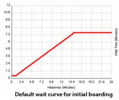
For transit services with a frequency of 60 vehicles per hour or more, the default wait time is set to half a minute. The default curve uses a constant wait time in this case because services with very small headways tend to have irregularly arriving vehicles, causing the relationship between wait time and headway to break down. The default wait curve for transfer points is half the headway of all services visiting the stop.
Rules for defining wait curves
The following rules apply to the coding/interpreting of wait curves:
-
The first coded X-Y pair must have a minimum X-value of 1 and minimum Y-value of 0.5.
-
Wait time (Y-axis) may not decrease as headway (X-axis) increases.
-
Linear interpolation applies between coded points.
-
The curve runs from the point (1- 0.5) to the first coded point. Wait time is fixed at 0.5 minutes for headways less than one minute.
-
Extrapolation beyond the last coded point occurs at the same gradient as immediately below that point.
Only the route-evaluation process uses wait curves.